Mastering EMC One Level at a Time
LEVEL 2
An important part of designing for electromagnetic compatibility is recognizing that the behavior of real electronic components and circuits can be significantly different than expectations or simulations based on the ideal components in a schematic diagram. This is especially true at higher frequencies (e.g., MHz frequencies and higher), where the effects of unintentional electromagnetic field coupling can no longer be ignored.
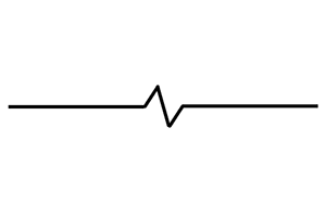
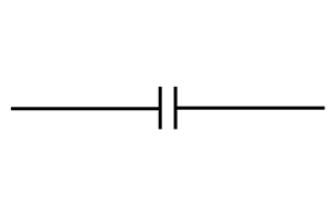
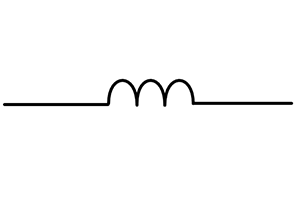
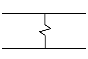
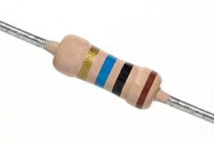
It's important to not only understand the concepts above, but also to be able to put them into practice. For example, you should learn to estimate the resistance of wires and circuit board traces to an order of magnitude. You should be able to estimate the self-capacitance of common objects in typical circuit board and system geometries. Inductance is a property of loops, so you should be able to identify relevant current loops and estimate their inductance.
Understanding that real components have parasitics is important, but it's just as important to be able to estimate the values of these parasitics (to an order of magnitude) in typical situations. Finally, the ability to trace intentional and unintentional current paths in a system is perhaps one of the most important skills required of an EMC or signal integrity engineer.
Here are four laboratory exercises you can complete that will help you get familiar with parasitic impedance parameters and current paths.
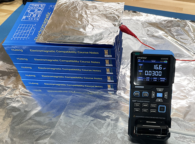
Lab Exercise 3: Measuring the Absolute Capacitance of an Object
Absolute capacitance and self-capacitance play an important role in EMC design and analysis. This demonstration (which could be assigned as a lab exercise) helps students see that absolute capacitance is something very real and measurable.
Laboratory Exercise 03: Absolute Capacitance Measurements
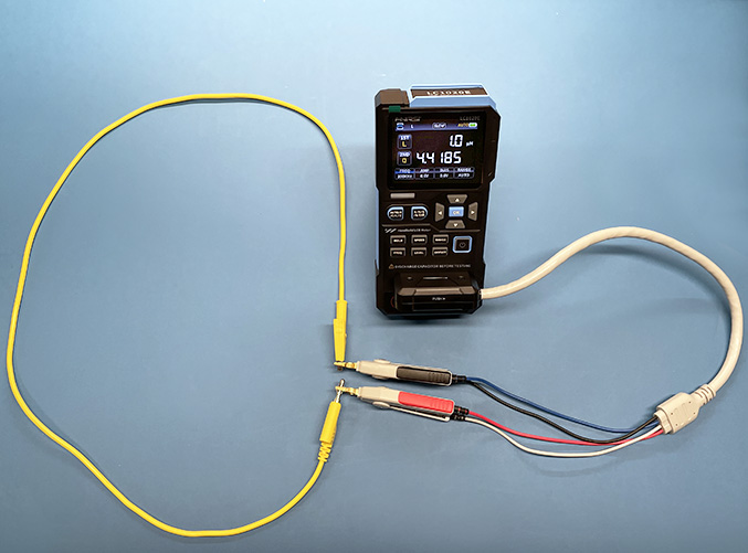
Lab Exercise 4: Measuring the Inductance of a Wire Loop
This demonstration (which could be assigned as a lab exercise) helps students get a feel for how changes in the size, shape, and wire thickness affect loop inductance.
Laboratory Exercise 04: Loop Inductance Measurements
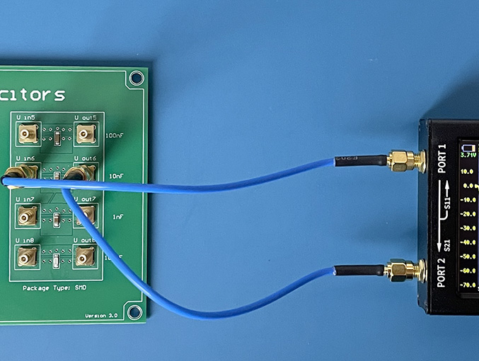
Lab Exercise 5: Measuring Component Impedance with a Vector Network Analyzer
This demonstration helps students to get a feeling for the effect that parasitics have on the electrical behavior of components. It also demonstrates how to measure these parasitics with a VNA.
Laboratory Exercise 05: Component Impedance Measurements
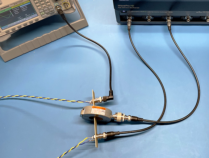
Lab Exercise 6: The Path of Least Impedance
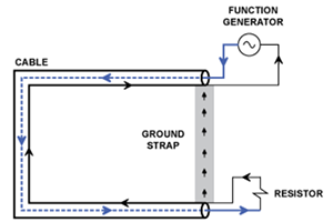
One of the more fundamental skills in EMC and signal integrity is anticipating where signal and noise currents flow. The exercise makes two important points: Currents return to their source, and currents take the path(s) of least impedance.
Laboratory Exercise 06: Path of Least Impedance