
Electronic Components
What is the difference between a resistance and a resistor? Resistance is the term we use to describe the real part of the ratio of the voltage across a device to the current through a device. Resistors are the components used in circuits to provide a specified amount of resistance.
Resistors have resistance. However, as every good EMC and signal integrity engineer knows, resistors in a circuit can also have significant inductance and/or capacitance. Figure 1 illustrates the magnitude of the measured impedance as a function of frequency for a typical 50-Ω resistor with axial leads.
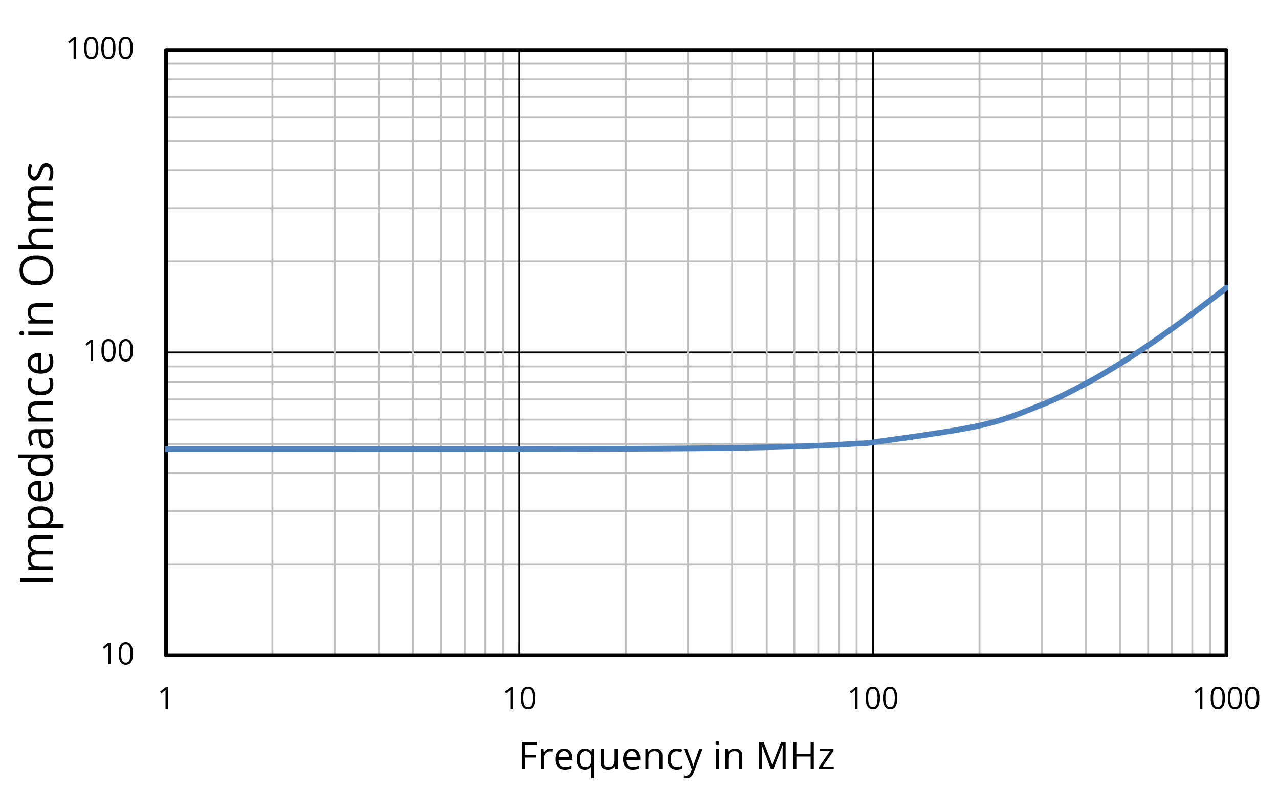
At frequencies below 100 MHz, the magnitude of the impedance is independent of frequency and has a value within 15% of the nominal resistance. However, above 300 MHz, the impedance increases with frequency, much as you would expect from an inductor. A simple circuit that models the behavior of the resistor is shown in Figure 2. The resistance in this circuit is close to the nominal value. However, the current flowing through the resistor and its connecting leads generates a magnetic flux that couples the circuit, introducing a small inductance in series with the resistance. Also, the voltage across the end caps creates electric field lines both inside and outside the resistor package. At higher frequencies or for larger resistances, the displacement current associated with these field lines bypasses the resistive, conduction current path and is represented by a capacitance in parallel with the resistance.

The inductance and capacitance in this resistor model are called parasitic components because they represent unintentional properties of the component. If we were to try to model the impedance of this resistor at higher frequencies, additional parasitic values could be introduced. However, the model in Figure 2 is generally sufficient to describe the behavior of most resistors within their useful frequency range.
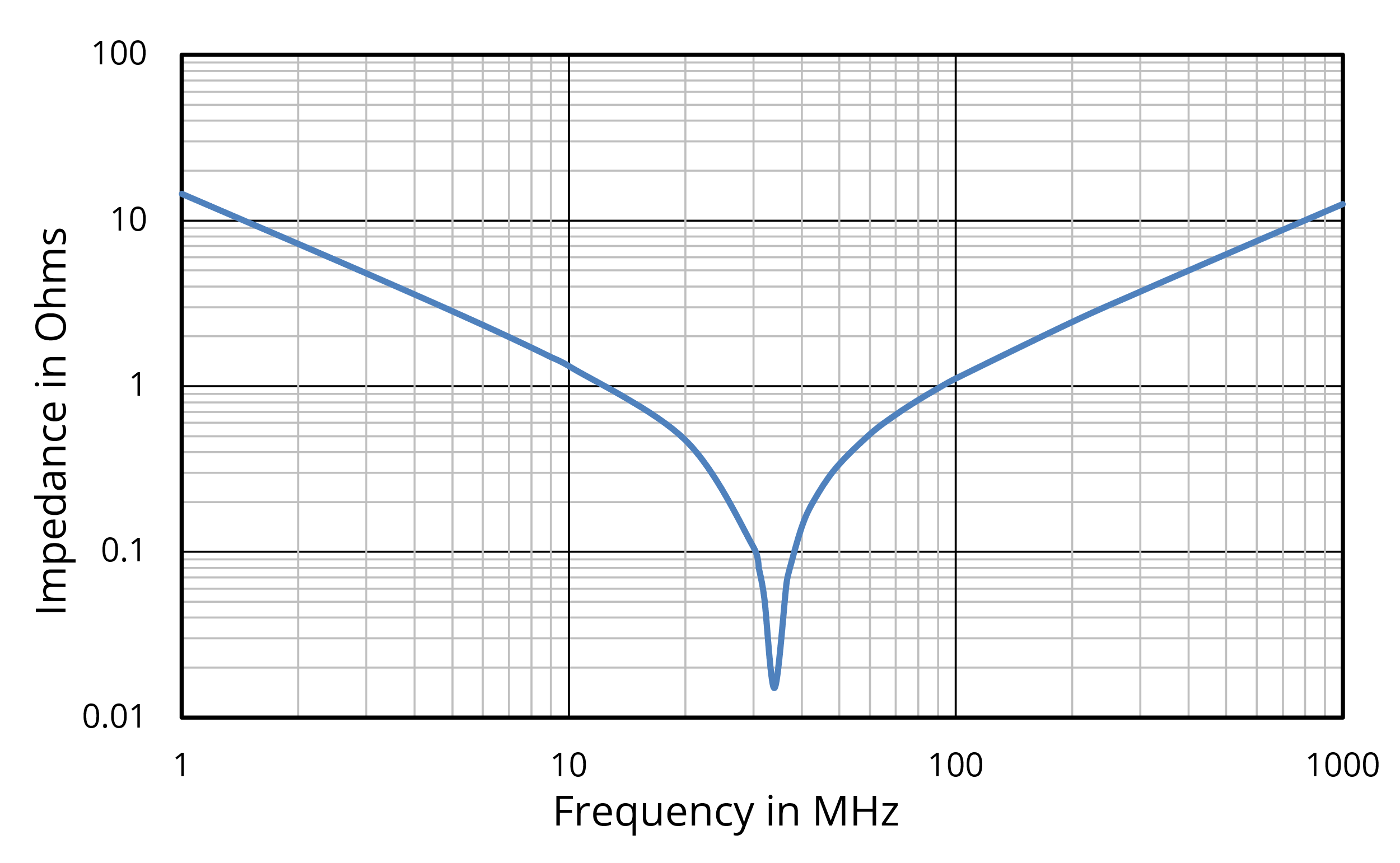
Figure 3 shows the measured impedance of a 0.01-µF surface-mount capacitor. Once again, at low frequencies, the impedance is what one would expect from a capacitor. However, above 100 MHz, the impedance increases with frequency, as if the device under test were an inductor.
An equivalent circuit for this capacitor is shown in Figure 4. In this circuit, the inductor represents the parasitic inductance associated with the magnetic flux coupling the capacitor’s package and connections to the rest of the circuit. The resistor represents the resistive loss in the package and connections.

While the inductance will change significantly depending on how the capacitor is connected to the circuit, the resistance is usually dominated by losses within the package. This value (the Equivalent Series Resistance or ESR) is often measured at specific frequencies and included in the capacitor specifications.
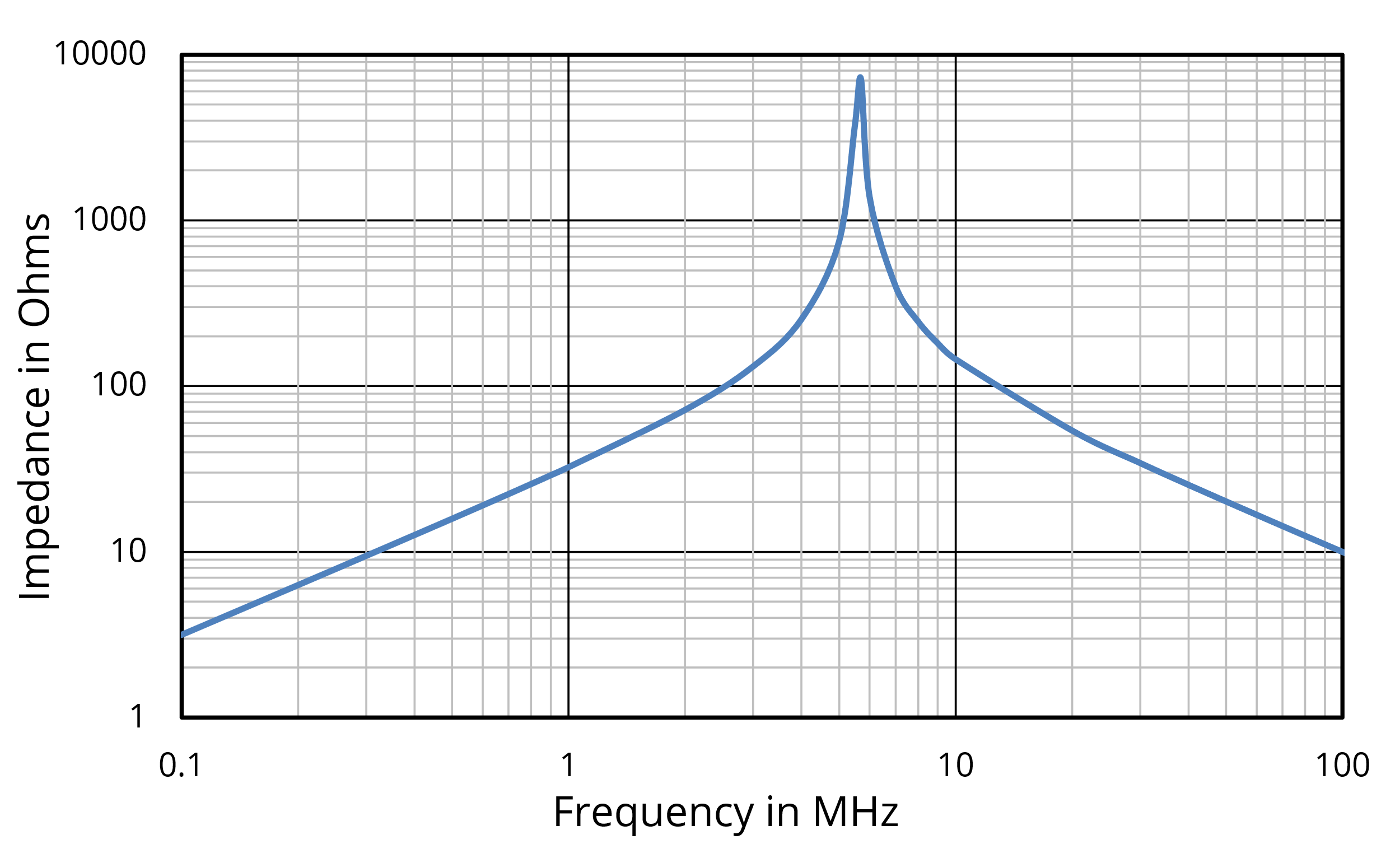
Inductors also have parasitic values. Figure 5 shows a plot of the impedance of a 5-µH surface-mount inductor. The equivalent circuit model is shown in Figure 6.

The parasitic capacitance represents electric-field coupling between windings and/or between the end caps of the package. Unless lossy ferrites are employed, the parasitic resistance is primarily due to conductive loss in the windings.
Types of Resistors
The materials and techniques used to manufacture resistors vary depending on the intended application.
Metal Film
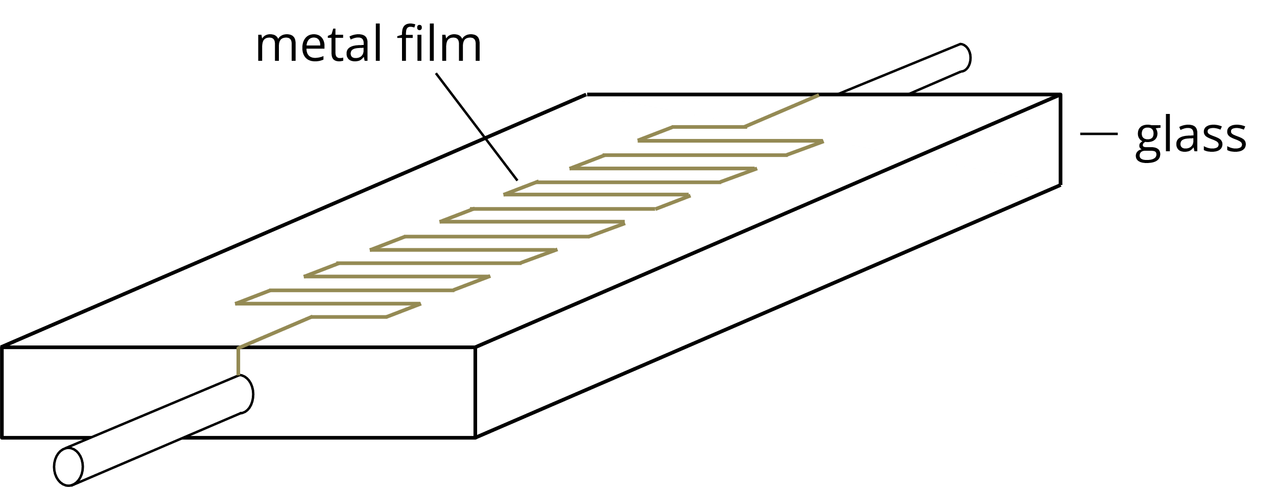
By far the most common type of resistor in use today is the metal film resistor. These resistors are manufactured by depositing a thin metal layer onto an insulating substrate, as illustrated in Figure 7. The resistance and power rating are controlled by varying the length and width of the metal film trace.
The advantage of metal film resistors is that their resistance can be precisely controlled. They are also generally the least expensive option for low- to moderate-power applications. A primary disadvantage of these resistors is that current transients whose peak power exceeds the resistor's power rating can easily destroy the metal film.
Carbon Composite
Carbon composite resistors are made by packing a conductive powder or paste between the two end plates of the resistor package. An advantage of this type of resistor is that it is not particularly susceptible to current transients. The peak power that these resistors can absorb is generally much higher than their steady-state power rating. Resistors of this type are well-suited for applications where components are likely to encounter voltage or current spikes.
Wire Wound
Wire-wound resistors consist of a lossy insulated wire wound in a helical shape around a ceramic core. The core helps to pull heat away from the wires. These resistors are used in applications that require them to dissipate large amounts of power. Their main advantage is their power-handling capability. However, they typically cost more than other types of resistors and can have significant parasitic inductance.
Types of Capacitors
The performance of capacitors depends to a great extent on the chemistry of the dielectric as well as the geometry of the conductors.
Ceramic
Look at any densely populated printed circuit board, and you will see a large number of capacitors. On most boards, the majority of these will be ceramic capacitors consisting of pairs of metal plates with a ceramic dielectric between them. Ceramic capacitors are relatively inexpensive and reliable. They can be divided into two classes depending on the characteristics of their ceramic dielectric. Class 1 capacitors (e.g., C0G and NP0) have relatively precise values that remain stable with changes in voltage and temperature. Class 2 capacitors (e.g., X5R and X7R) have higher permittivity dielectrics, so larger nominal values can be achieved within a given package size. On the other hand, the capacitance of Class 2 capacitors can vary significantly depending on the applied voltage or temperature.
Electrolytic
Electrolytic capacitors employ a dielectric material with a higher permittivity than ceramic materials, but only in one polarity. In standard electrolytic capacitors, the electrodes are oxidized metal surfaces separated by paper soaked with a liquid or a gel electrolyte. Because they are polarized, electrolytic capacitors can only be used in situations where there is a DC bias voltage. The higher permittivity of the dielectric allows larger capacitance values to be obtained for a given package size. Generally, the larger capacitors on a printed circuit board (physically and by nominal value) are electrolytics. Their main advantage is their large nominal value and relatively high voltage ratings. However, they do not exhibit the same temperature and frequency stability as other types of capacitors.
Polymer
Polymer capacitors are a form of electrolytic capacitor utilizing a solid electrolyte. A common polymer capacitor is the tantalum capacitor (made with electrodes that contain the element tantalum). Like other electrolytic capacitors, they pack a lot of capacitance into a small package. However, polymer capacitors tend to have better temperature and frequency characteristics than other electrolytics. The main disadvantages of polymer capacitors are their relatively high cost and susceptibility to voltage transients.
Film
Film capacitors employ an insulating plastic film as the dielectric. The film may be sandwiched between two layers of metal foil, or the metallization may be vacuum-deposited on the surface of the film. Film capacitors generally have larger package sizes than ceramic or electrolytic capacitors with the same nominal capacitance. However, they tend to be more stable and reliable than electrolytic capacitors, and they are non-polarized. Film capacitors are typically better suited for high-energy applications than ceramic capacitors due to their physical size and capacity to carry large currents.
High-Voltage
Capacitors designed to withstand very high voltages employ dielectric materials such as mica that can withstand strong electric fields without breaking down. They may also utilize more electrodes with greater spacing. Their primary disadvantages are their cost and their relatively large package size.
Supercapacitors
Supercapacitors (also called ultracapacitors or electric double-layer capacitors) store electrical energy in the space between small conductive particles. Rather than traditional plates, the electrodes in a supercapacitor are formed by a chemical reaction. As a result, these capacitors can have extremely high nominal values (e.g., several farads or more) in a relatively small package. They are sometimes used to replace backup batteries in electronic equipment. Supercapacitors are relatively expensive, and they can be dangerous if their terminals are accidentally shorted.
Types of Inductors
Inductors come in a variety of shapes and sizes, but most of them have a wire coil. The diameter of the wire, the shape of the coil, and the number of turns all play a role in determining the component’s inductance as well as its parasitic resistance and capacitance. Another important parameter is the properties of the core material within and around the windings.
Ferrite Core
The most common type of inductor found in electronic circuits consists of a thin wire wound around a ferrite core. The ferrite material has a high permeability, which increases the amount of inductance for a given loop area and number of turns. This permits higher values of inductance in smaller packages than one could obtain without the ferrite material. However, at high current levels, the ferrite material can saturate, causing its effective permeability to drop significantly. This nonlinear behavior can result in the creation of signal harmonics and other problems.
Shielded inductors surround the windings with ferrite. This helps to contain the spread of magnetic field lines and reduces the likelihood of unwanted coupling to nearby components and circuits.
Air Core
Air core inductors consist of wire wrapped around an air (or any non-ferrous) core. They are employed in situations such as high-frequency amplifier designs, where linear behavior is critical, and in power circuits, where the inductor must handle high currents.
SMT Component Sizes
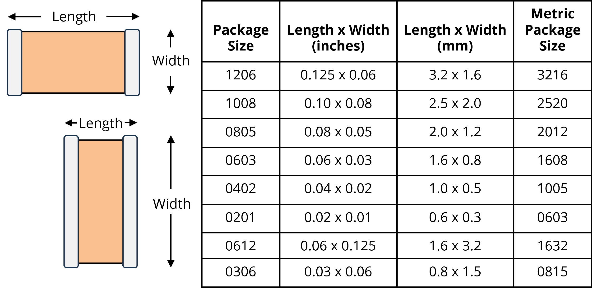
The sizes of passive rectangular Surface-Mount Technology (SMT) components, such as resistors, capacitors, and inductors, are often specified using four-digit numbers. For example, a small high-frequency decoupling capacitor might come in an 0402 (pronounced oh-four-oh-two) package size. A larger bulk capacitor might have a 1206 (pronounced twelve-oh-six) package size.
In most cases, the first two digits refer to the length of the package, and the second two digits correspond to the width of the package specified in hundredths of an inch. For example, the dimensions of an 0402 component are 0.04 × 0.02 inches, and the dimensions of a 1008 package are 0.10 × 0.08 inches. Very small components have five- or six-digit codes to include all leading zeros. So, the nominal package size of a component that is 0.010 by 0.005 would be 01005, and the nominal package size of a 0.008 × 0.004 component would be 008004.
The length of a two-terminal device is defined as the distance between its two terminals. In most cases, the length is greater than the width. However, in reverse aspect ratio components, the width is greater than the length (e.g., 0612). These components facilitate low-inductance connections by making the current path through the device shorter and wider. Wider endcaps also encourage multiple via connections to the solder pads.
While this notation, based on imperial units, is convenient and widely used, there is a growing trend toward using a similar metric notation. The metric notation specifies the length and width in tenths of a millimeter. For example, a component with an 0402 metric size code is 0.4 × 0.2 mm. When specifying a component size using a four-digit code, it is important to be clear whether the code is based on imperial or metric units. A few common SMT package sizes and their dimensions are listed in Figure 8.