Looking for a comprehensive hands-on learning experience?

Looking for a self-paced study option?

Mastering EMC One Level at a Time
It's not necessary to be an expert with decades of experience to make good EMC design decisions. On the other hand, a little bit of EMC knowledge can be worse than knowing nothing at all. That is particularly true if that EMC knowledge consists of "helpful" design guidelines gleaned from internet sources such as application notes, LinkedIn, AI chatbots, or PCB manufacturer websites. Many of the worst product designs we've reviewed were the result of well-meaning engineers following advice they found on the internet.
The path to becoming an EMC expert starts with mastering the basics and then systematically progressing to more advanced topics. One such path is outlined by the levels described below. The "learn more ..." links for each level take you to web pages that outline the topics and provide links for further study. These pages are still under construction, but some of the links and target dates for completion are provided.
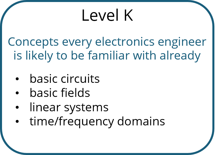 An EMC education starts with a basic understanding of circuits, fields, and linear systems. These topics are typically covered in an undergraduate engineering or engineering technology curriculum. We review some of these concepts on this website, but there's no substitute for a good ABET-accredited engineering education.
Learn more ...
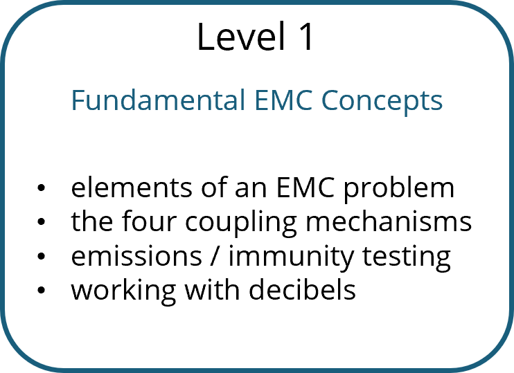 This section describes the most fundamental EMC concepts, including the three elements of an electromagnetic interference problem and the four electromagnetic coupling mechanisms. It also includes brief descriptions of emissions and immunity test set-ups and requirements, as well as the basic definitions and acronyms that are important to anyone working in this field.
Learn more ...
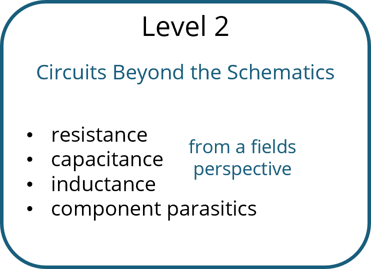 Electrical engineers are generally familiar with resistors, capacitors, and inductors, but interconnects, wires, and other conductors also have resistance, capacitance, and inductance. These properties are often insignificant when doing a circuit analysis, but EMC engineers must be aware of them and recognize when these properties become important. To paraphrase an old EMC adage, "EMC is about the components that are not in the schematic." On the other hand, good EMC engineers can often model unwanted or unexpected field coupling by adding important parasitic elements to a circuit schematic.
Learn more ...
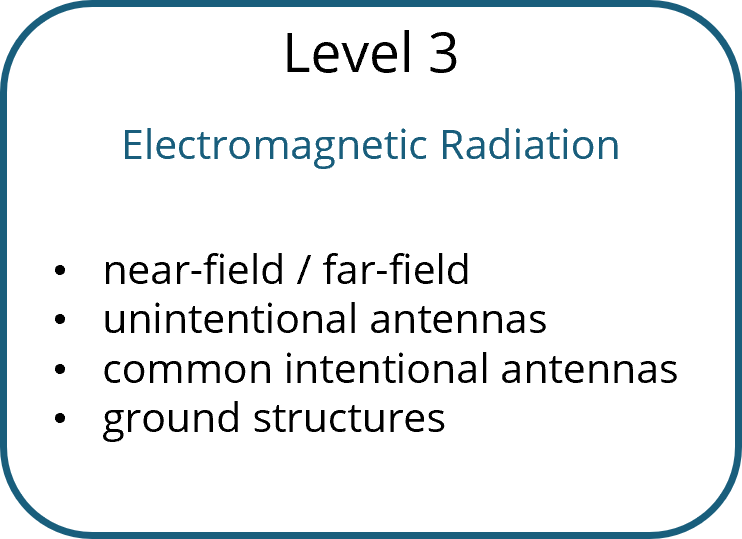 Electromagnetic radiation plays a key role in many electromagnetic interference problems. Any conductor carrying a time-varying current can radiate, but the amount of radiated power is greatly dependent on the geometry of the structure and the way it's driven. Meeting radiated emissions and immunity requirements is largely about identifying the unintentional antennas in the system and not coupling to them. Quantifying the radiated coupling to or from a structure can be a complex process. On the other hand, simply identifying efficient radiation sources and eliminating them can be relatively straightforward.
Learn more ...
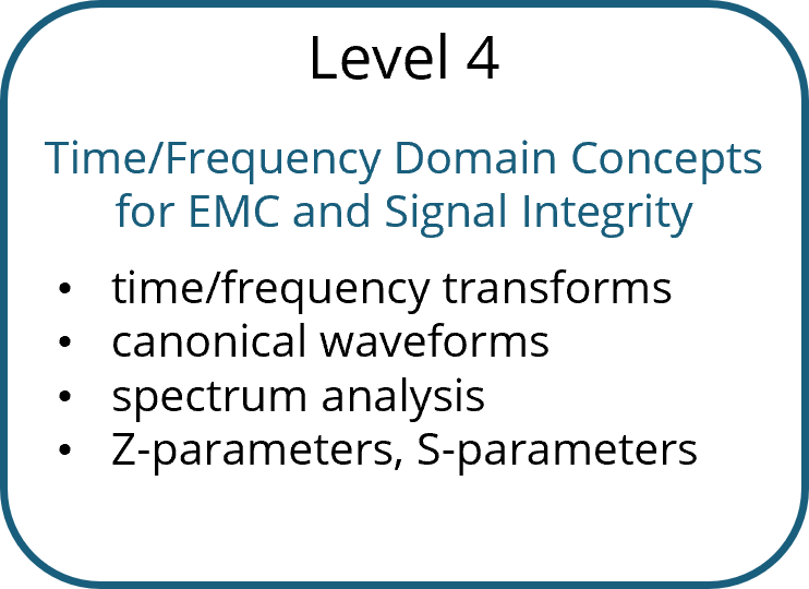 All engineering fields rely heavily on linear system modeling and analysis in both the time and frequency domains. The signals and noise in electronic systems tend to rely on a relatively limited set of waveforms. Recognizing these waveforms and being familiar with how they look in both the time and frequency domains is an important skill for EMC and signal integrity engineers.
Learn more ...
 Signals travel with finite propagation velocities. For many circuits, the delay associated with the finite propagation velocity is negligible. When the delay cannot be neglected, steps must be taken to preserve the integrity of the signal.
Learn more ...
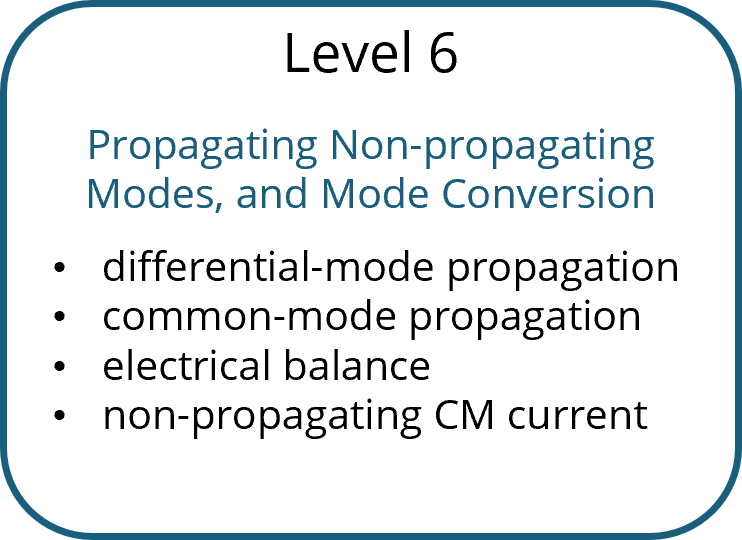 Crosstalk in cables or between circuits on a circuit board can be due to electric-field coupling, magnetic field coupling, common-impedance coupling, or some combination of these coupling mechanisms. Fortunately, it's relatively straightforward to model and is unlikely to be an issue if crosstalk calculations are performed early in the product design cycle.
Learn more ...
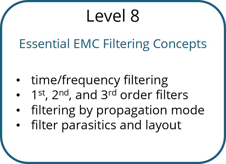
 Intentional signals and unintentional noise often utilize different modes of propagation. Preventing mode conversion and filtering specific modes are important methods of reducing electromagnetic interference.
Learn more ...
 A good grounding strategy is an important part of ensuring that a product will meet its EMC requirements. Unfortunately, the term "ground" has different meanings in different situations. Safety ground, circuit ground, and grounding for EMC compliance are not the same things. Applying the rules for one type of ground to another type of ground can compromise the safety, signal integrity, and electromagnetic compatibility of a system.
Learn more ...
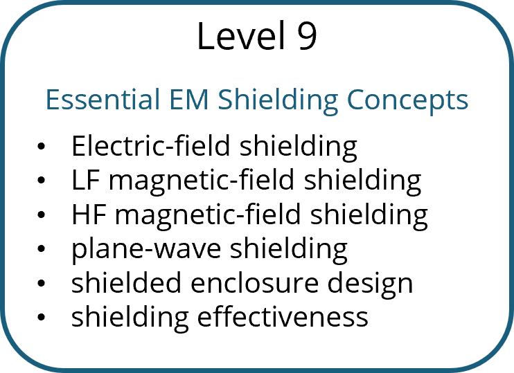 Filtering is an important part of meeting EMC and signal integrity requirements. We rely on filtering to attenuate noise while passing the intended signal or power waveforms. Since EMC filters are generally required to operate over wide bandwidths, component selection and board layout play an important role in determining how well a filter will perform in any given application.
Learn more ...
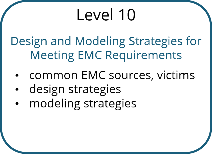 Shielding is often utilized to reduce electric or magnetic field coupling in a system. Selecting the correct shielding material, placing it appropriately, and connecting it properly are all important skills for an EMC engineer. However, the correct material, placement, and connections depend on the coupling mechanism being targeted. Poorly designed or placed shields can actually enhance the coupling they were intended to prevent.
Learn more ...
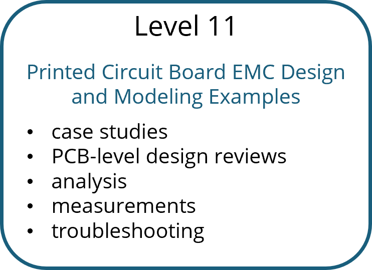 Being well-versed in the theory driving EMC design and modeling is important, but to become an expert in EMC, you have to be able to apply this theory to real products. For this, there is no substitute for experience. This section covers real issues that arise when making layout and layer stack-up decisions for printed circuit boards. These decisions must be based on the specific application and its requirements. It's not about following design guidelines. It's about identifying potential EMC problems, quantifying them using appropriate models, and making the decisions necessary to ensure compliance with EMC requirements.
Learn more ...
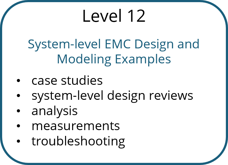 System-level design decisions often have a major impact on whether a product meets its EMC requirements. Enclosure design, materials, cables, connectors, signal protocols, and thermal management options are just a few of the design choices that can make the difference between a compliant and a non-compliant product.
Learn more ...