
Chapter 2 Lab Exercise: Component Impedance Measurements
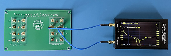
One of the more important concepts in EMC is that electronic components have parasitics that determine their behavior at high frequencies. If you happen to have access to an impedance analyzer that will measure the complex impedance of small components over a wide range of frequencies, students can measure a variety of resistors, capacitors, and inductors to get a feeling for the conditions where these parasitics become important. If you do not have access to an impedance analyzer, similar measurements can be made using a low-cost vector network analyzer and a test fixture.
The test fixture should have 50-Ω input and output ports. For low-impedance components, the component to be tested will be connected in parallel with the ports. In this configuration, the impedance is approximately equal to
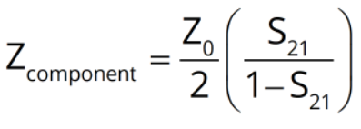 .
.
For high-impedance components, the component to be tested will be connected in series with the ungrounded terminals of each port. In this configuration, the impedance is approximately equal to,
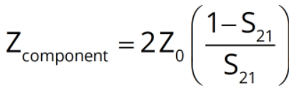 .
.
Preparation: The test fixture can be provided to the students or designed and built by the students. Students should derive the equations relating measured values of S21 to impedance.
Equipment Required:
- vector network analyzer
- test fixture to hold SMT or pin-in-hole components
Procedure:
Step 1: The frequency range of the measurement will depend on the type of components being measured and the test fixture. Typically, this range might be from 100 kHz to 100 MHz. Students should perform an open, short, and through calibration of the VNA and empty test fixture in the frequency range of the measurement.
Step 2: Connect a small-valued resistor (e.g., 5 ohms) to the parallel test fixture. Attach the VNA to the input and output ports and measure S21. The measured value should start flat and then rise with frequency at 20 dB/decade. Choosing a value of S21 in the flat region, calculate the value of R. Choosing a value of S21 in the rising region, calculate the parasitic inductance.
Step 3: Connect a capacitor (e.g., 0.1 μF) to the parallel test fixture. Attach the VNA to the input and output ports and measure S21. The measured value should start out falling with frequency at 20 dB/decade, then go through a resonance, and then rise with frequency at 20 dB/decade. Choosing a value of S21 in the falling region, calculate the value of C. Choosing a value of S21 in the rising region, calculate the parasitic inductance.
Step 4: Connect an inductor (e.g., 0.1 μH) to the series test fixture. Attach the VNA to the input and output ports and measure S21. The measured value should start out falling with frequency at 20 dB/decade, then go through a resonance, and then rise with frequency at 20 dB/decade. Choosing a value of S21 in the falling region, calculate the value of L. Choosing a value of S21 in the rising region, calculate the parasitic capacitance.
Step 5: Connect the inductor to the parallel test fixture. Can the impedance still be determined from S21? What values are obtained?
Step 6: Experiment by measuring components with different nominal values. Try modifying the connection to the capacitor to increase or decrease the connection inductance. Can you see the impact of this change in the measured results?
Step 7: Disconnect Port 2 and try measuring the impedance of these components based on S11 measurements. The formula to use in this case is,
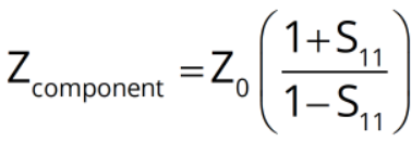 .
.
Notes:
The results will depend on the quality of the test fixture. In the case of the parallel test fixture, we are actually measuring the mutual inductance between the input and output loops. You can ask students to explain why this is effectively equal to the self-inductance of the component.
The test fixture shown in the photo is available as part of a PCB Experiments Kit from the IEEE EMC Society.