EMC Question of the Week: November 16, 2020
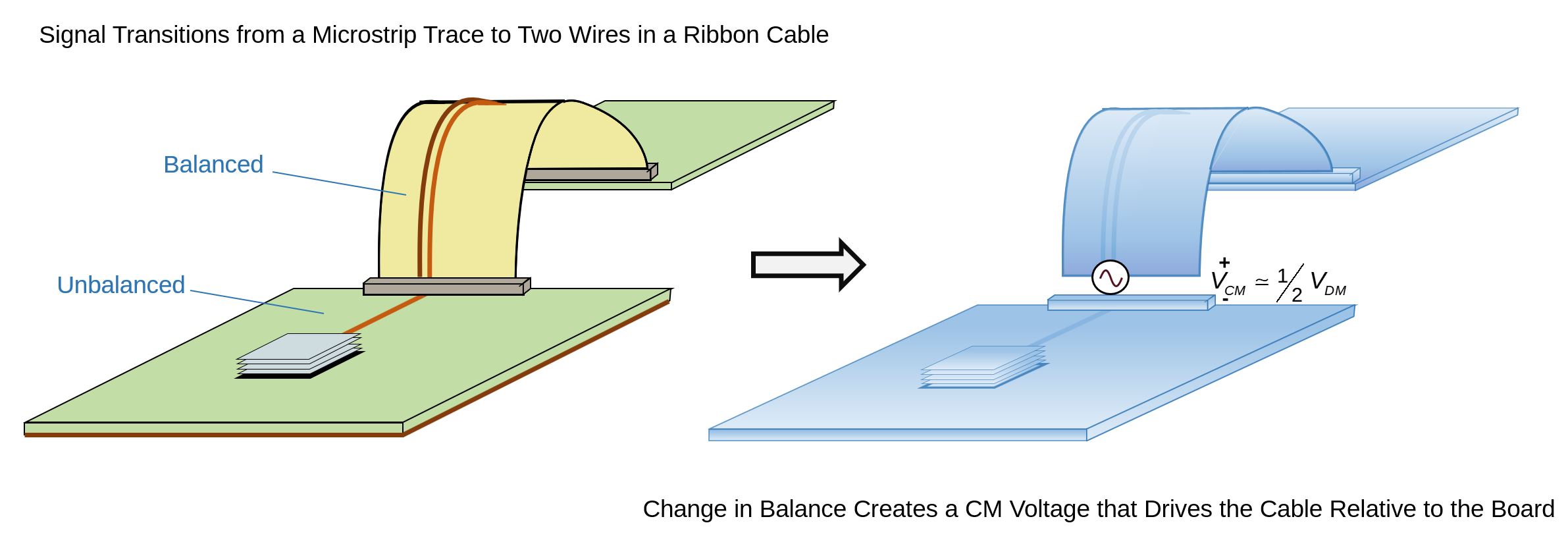
A 100-Mbps single-ended signal propagates from its source to the edge of a circuit board on a microstrip trace. At the board edge, it transitions to a ribbon cable where the signal current flows on one wire and the return current flows on an adjacent wire 2 mm away. In this situation, the common-mode voltage that drives the ribbon cable relative to the circuit board is
- half the signal voltage
- proportional to the connector inductance
- proportional to the connector resistance
- negligible
Answer
The best answer is "a". When a signal transitions from a very unbalanced transmission line to a very balanced transmission line, a common-mode voltage is developed that is approximately half the signal voltage. The exact value of the voltage can be determined by multiplying the change in the current division factor (or imbalance factor) by the signal voltage. This voltage is independent of the connector inductance or resistance (at least for any reasonable connector designed to carry a 100-Mbps signal). At very low frequencies, this voltage might not be important; but at 100 Mbps, where less than 1 mV can cause a radiated emissions failure, driving the cable with half the signal voltage is not usually "negligible."
Additional current return wires in the ribbon cable can make it more imbalanced and reduce the voltage driving the cable. For example, adding another current return wire on the other side of the signal wire would typically reduce the cable-driving voltage by 4-8 dB. But additional ground wires would have a diminished effect, so a ribbon cable with many ground wires would still be driven by a significant fraction of the signal voltage.
On the other hand, a ribbon cable with a current return plane under the signal wires would be largely unbalanced, resulting in very little common-mode voltage. For this reason, flexible 2-layer circuit boards are often a great alternative to ribbon cables for carrying high-frequency single-ended signals. You can learn more about electrical balance and DM-to-CM mode-conversion in the tutorial, Introduction to Imbalance Difference Modeling.
Have a comment or question regarding this solution? We'd like to hear from you. Email us at