Why You Should Be Cautious about Using EMC Design Rules
 As much as we hate to admit it, EMC engineers and printed circuit board (PCB) designers rely heavily on design rules (we prefer the term guidelines) when designing or evaluating PCBs or diagnosing EMC problems. Unfortunately, there are nearly as many design guidelines as there are design engineers. Some guidelines are based on circuit or radiation models, some are based on experience, and others have no known origin. A few guidelines are very important and can nearly always be applied. Others apply only to specific situations and are not appropriate in general. In Dr. Hubing's "Grounding and Shielding" class, students are given a list of EMC design guidelines that are widely used in the electronics industry. Each guideline is discussed in class so that students are familiar with the reasons for the guideline and they know how and when each guideline should be applied. Students are then assigned a homework problem where they are asked to review a simple board that has a specific EMC problem and re-layout the board to improve its performance. Every semester most students in the class turn in a new design that is worse than the original!
"Some of the worst printed circuit boards we've seen were designed by engineers who were trying to comply with a list of EMC design rules."
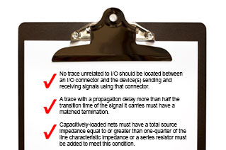
The problem is not that students ignore the guidelines or that the guidelines are bad. The problem stems from the urge to try to comply with as many guidelines as possible. Since guidelines involve making trade-offs, a board that complies with 90% of the guidelines may be much worse than a board that complies with only one or two guidelines. Good board design is not a matter of complying with as many guidelines as possible. What's important is to comply with the guidelines that really matter in your particular application. For example, there are several design guidelines on the list that deal with printed circuit board decoupling. These may be critically important to some board designs, but they might be ignored without consequence in boards where power bus noise is not an issue. Another guideline on the list states that high-speed circuitry should not be located between connectors on the board. In some designs, you could do everything else perfectly and violating this one guideline could result in excessive radiated emissions.
It is important for an EMC engineer or board layout expert to be able to recognize which guidelines absolutely must be complied with and which guidelines are less important for any given application. The ability to do this comes from recognizing where the likely sources, antennas and coupling paths are in any given design. Rather than relying on general design guidelines, a more systematic approach that relates EMC performance requirements to design criteria is preferred. One such approach is the Design for Guaranteed EMC Compliance method, which is essentially a combination of computer modeling and targeted guidelines for systematically ensuring that no circuit or component can contribute to a system's inability to meet an EMC specification.
The design guidelines presented on these pages are meant to inform and entertain. Please don't design your next product using these guidelines and then complain to us when it fails to meet your EMC requirements (or perhaps fails to even work). We won't say we told you so, but we may refer you back to this web page.
