EMC Question of the Week: June 22, 2026
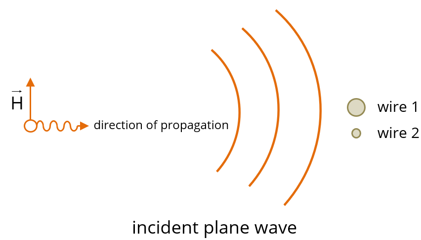
An electromagnetic plane wave is incident on a long parallel-wire transmission line. The two wires have different diameters. The incident E-field striking both wires has the same amplitude and phase (i.e., broadside incidence as indicated in the figure). Which of the following statements is correct about the common-mode and differential-mode currents induced in the wires?
- ICM = I1 + I2
- IDM = 0
- VDM = 0
- all of the above
Answer
The best answer is “d.” This common-mode excitation induces a common-mode current. The current induced on each wire is not the same, but the common-mode current is (by definition) the sum of the currents on the two wires. There is no differential-mode voltage or current. Most importantly, from the viewpoint of an EMC engineer, a differential receiver connected anywhere along this line would not observe any interference.
If you concluded that there was a differential-mode and that IDM and/or VDM were not zero, it is probably because you applied a definition of IDM that is only valid for balanced transmission lines. For balanced transmission lines, IDM = 0.5 (I1-I2). Since I1 does not equal I2, this equation suggests that a differential-mode current is induced. But that definition can't be applied here.
The definitions of VDM and ICM are the same for both balanced and unbalanced transmission lines: VDM = V1 - V2 and ICM = I1 + I2. However, the definition of the differential-mode current is a function of the amount of imbalance. Attempting to apply the balanced definition of IDM to unbalanced transmission lines can be misleading because the resulting currents no longer describe independent propagation modes. This creates an inability to separate common-mode and differential-mode components and can be responsible for some very bad EMC or signal integrity design decisions.
There's more information on the definition of common-mode and differential-mode voltages and currents in the article Introduction to Imbalance Difference Modeling. An important point is that mode conversion is not caused by imbalance. Mode conversion only occurs when there is a change in the amount of electrical balance. For a more thorough introduction to propagation modes, mode conversion, and how they impact EMC design decisions, we recommend the book Electromagnetic Compatibility Course Notes.
Note: If our example had used a coaxial cable geometry instead of an unbalanced wire pair, the answer would have been the same. In that situation, most EMC engineers would intuitively understand that VDM = 0 and that all of the induced current is a common-mode current.
Have a comment or question regarding this solution? We'd like to hear from you. Email us at