EMC Question of the Week: May 26, 2025
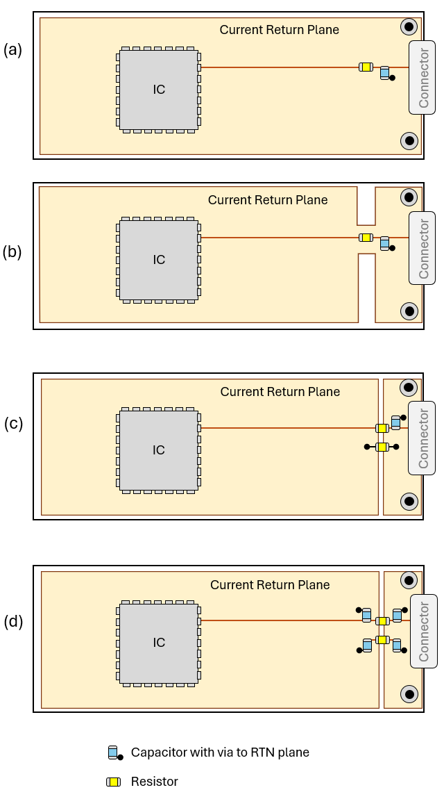
A 1-Mbps digital signal is transmitted across a circuit board, through a connector, and on to a shielded wiring harness. An RC low pass filter is used to limit the bandwidth of the transmitted signal. Which filter layout gives this product the best chance of meeting its EMC requirements?
- RC filter with solid return plane
- RC filter with return plane partially gapped
- RC filter with resistor on return conductor
- RC filter on both signal and return conductors
Answer
The best answer is “a.” A pretty good rule-of-thumb is that single-ended signals should never have an intentional impedance in their return path. Impeding the return current produces a voltage across the impedance. In these examples, that voltage drives the current return plane (and all components on the board) relative to the chassis ground. This voltage can be the source of radiated emissions problems and/or create crosstalk between the filtered source and other signals sharing the harness.
In the field of EMC, there are very few design rules that always apply. However, situations where it is "a good idea" to intentionally impede the high-frequency return current of a single-ended signal are extremely rare.
Note: It's true that (b) does not significantly impede the high-frequency return current, but the gaps in the plane serve no useful purpose. Gapping the region of the return plane near a connector like this is virtually never a good idea.
Have a comment or question regarding this solution? We'd like to hear from you. Email us at