EMC Question of the Week: December 2, 2024

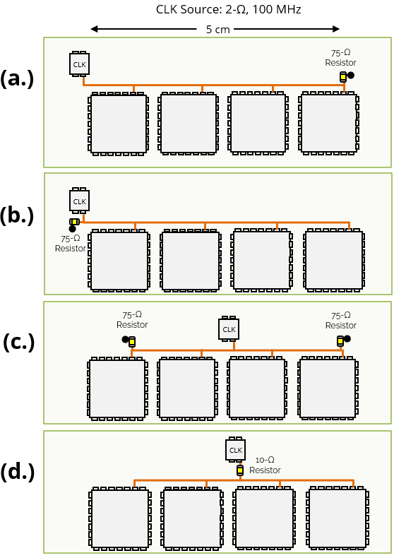
A 2-Ω, 100-MHz clock source drives 4 CMOS inputs on a circuit board over a distance of about 5 cm. The trace impedance is about 75 Ω. Which terminating resistor(s) configuration shown in the figure is appropriate?
- parallel 75-Ω resistor at far end
- parallel 75-Ω resistor at source end
- parallel 75-Ω resistor at both ends
- series 10-Ω resistor at source end
Answer
The best answer is “d.” Each CMOS input has a capacitance of about 5 pF, so the total capacitance being driven (including the trace capacitance) is about 30 pF. With the 10-Ω series resistor, the source resistance is about 12 Ω, so the transition time is about 2.2 x 12 Ω x 30 pF = 800 ps. The maximum propagation delay with the clock driver centered is roughly 2.5 cm ÷ 2 x 1010 cm/s, which is less than 200 ps. This transition time is about 4 times the propagation delay, so there is no need to use controlled-impedance traces or matched terminations.
The other three options do not control the transition time of the clock signal. A 2-Ω source driving 30 pF yields a transition time that may be as fast as 2.2 x 2 Ω x 30 pF = 130 ps. If the signal were allowed to transition this quickly, matched terminations and controlled impedance traces would be required. in this case, the clock would draw more power, and the signal would have significant harmonic content up to and above 2 GHz. This would make it more difficult to meet EMC and signal integrity requirements.
Note that if it were necessary to drive this signal a much greater distance (e.g., 25 cm), matched terminations would be required. In this case, it would be best to use a clock driver with a controlled transition time that was matched to the trace impedance. In this case, the best layout would depend on the specific application. Factors to be considered would include the strength of the driver and the impact of the propagation delay on the clock timing.
Have a comment or question regarding this solution? We'd like to hear from you. Email us at
