EMC Question of the Week: October 14, 2024
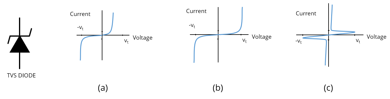
Which of these three V-I curves corresponds to the transient voltage suppression (TVS) diode schematically represented in the figure?
- (a)
- (b)
- (c)
- (b) or (c)
Answer
The best answer is “a.” The unipolar TVS diode schematically represented in the figure is a voltage-limiting device with a threshold voltage equal to its reverse breakdown voltage. With a forward-bias, it starts conducting at voltages greater than about 0.3 - 0.5 volts like most other diodes. This device can be used to protect circuits with a DC bias. Or, two of them in series (face-to-face) can provide bi-polar transient protection.
The V-I curve in the middle is typical of a metal oxide varistor (MOV), which is inherently a bipolar voltage-limiting device. Two face-to-face TVS diodes in series would have a similar V-I curve. If both diodes were in the same physical package, that device might be described as a bipolar TVS diode, but schematically it would still be represented as two unipolar diodes pointed towards each other.
The V-I curve on the right is a crowbar device (as opposed to a voltage-limiting device). This V-I curve would be typical of a thyristor or a gas discharge tube. Crowbar devices are generally capable of suppressing higher-energy transients without being damaged. TVS diodes have the advantage that they can turn on and off more quickly than crowbar devices.
Have a comment or question regarding this solution? We'd like to hear from you. Email us at