EMC Question of the Week: July 8, 2024
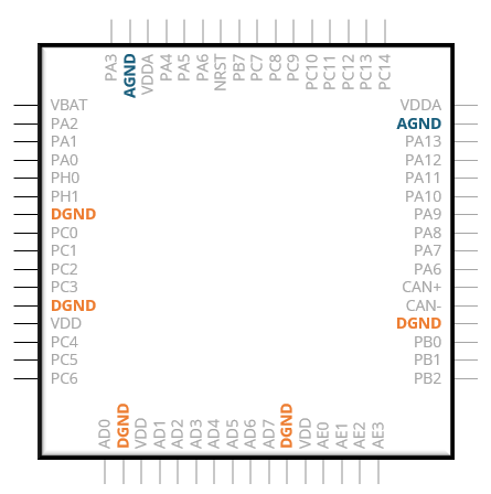
When a component on a multilayer board has two types of ground pins (e.g., analog and digital, or digital and power) they should all be connected to the same solid ground plane(s) unless
- the datasheet says otherwise
- the clock frequency is > 1 MHz
- the board has multiple ground planes
- you can prove that they must be isolated
Answer
The best answer is “d.” On a board that has a solid ground plane on at least one layer, it is almost always best to connect every component ground pin directly to that plane. It is unlikely that significant noise will be coupled from one circuit to another due to common-impedance coupling in the plane. On the other hand, splitting the plane or referencing circuits to two different grounds can allow voltages to develop that ultimately result in radiated or conducted emissions problems.
While there are measures that can be taken to ensure EMC compliance of a board with multiple grounds, these measures tend to add cost, take up space, and decrease the overall reliability of the system. It's best to have one common reference for all of the circuits on the board whenever possible.
The EMC-related board layout advice in component datasheets is generally pretty bad and should never be followed blindly. This is particularly true about advice related to the grounding of components and systems. Never isolate two grounds just because the datasheet says it is necessary or desirable.
It is relatively easy to determine whether isolated current returns (i.e., grounds) are necessary to prevent common-impedance coupling between two circuits. Multiply the worst-case current that the "noisy" circuit could put on the plane by the worst-case (maximum) plane resistance. If the resulting voltage is high enough to disrupt the "victim" circuit, then provide an isolated current return for either the source or the victim. Half-ounce copper planes will generally have a point-to-point resistance well below 1 mΩ. So, 10 A of current would generally produce less than 10 mV of noise across the plane.
The calculation above works well for low-frequency, common-impedance coupling. At high frequencies (e.g., > 1 MHz), or for other coupling mechanisms (E-field or H-field), we don't need to do this calculation. At high frequencies, the current does not spread out on the plane and common-impedance coupling can be avoided by careful trace routing. And, if field coupling is a concern, it is usually better to have one common ground. Isolating the grounds generally doesn't reduce field coupling.
In most situations, multilayer circuit boards should have solid ground planes that are the shared return path for all single-ended signals and DC power distribution. In rare cases where it is necessary to isolate a low-frequency current return to prevent common-impedance coupling, it's relatively straightforward to calculate the worst-case coupling and prove that the isolation is necessary.
Have a comment or question regarding this solution? We'd like to hear from you. Email us at