EMC Question of the Week: February 5, 2024
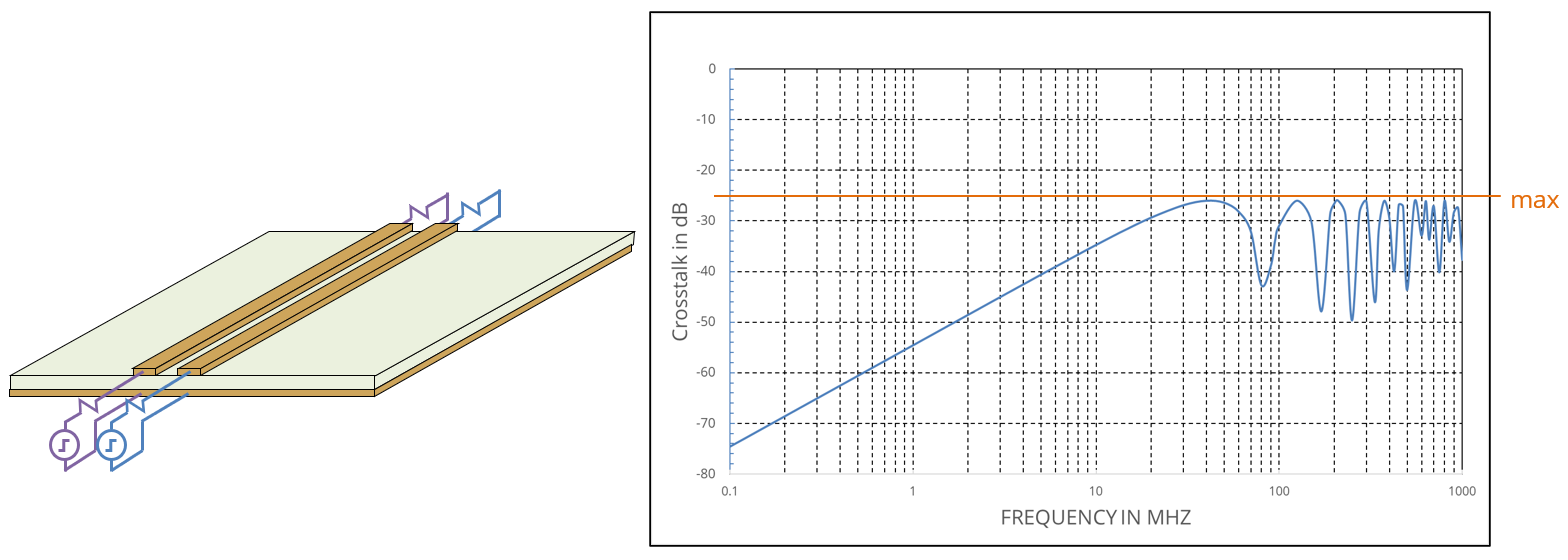
To evaluate the worst-case high-frequency coupling between two long microstrip traces routed side by side on a circuit board, it's best to use a
- 2D static electric-field solver
- 2D static magnetic-field solver
- 3D full-wave solver
- DC resistance measurement
Answer
The best answer is “a.” To evaluate the worst-case coupling, we need to determine the per-unit-length self and mutual capacitances and the per-unit-length self and mutual inductances of the trace pair. 2D electric-field solvers are the ideal tool for making this determination. They can provide the self and mutual capacitances directly from the cross-sectional geometry and the permittivity of the dielectric. The self and mutual inductances can be determined indirectly by removing the dielectric and noting that the self and mutual inductances are related to the self and mutual capacitances by the velocity of propagation in a homogeneous environment. Thus, one solver can be used to calculate the most important parameters quickly and accurately.
2D static magnetic-field solvers suffer from two drawbacks. First, they can't account for the dielectric permittivity. Second, the DC current distribution is not the same as the high-frequency current distribution. Unless the solver has a method for forcing the current to emulate a high-frequency distribution, it will not accurately calculate the high-frequency self and mutual inductances.
3D full-wave solvers are not a good choice for simulating long transmission lines. In theory, one could use a lot of elements to model a section of the line long enough to neglect the end effects. However, to accurately determine the per-unit-length parameters, the elements would be very small relative to a wavelength and the cumulative error would be relatively high. For this reason, many commercial 3D software packages include non-full-wave features to help with transmission line modeling.
Of course, with a 3D full-wave solver, the crosstalk can be calculated directly by modeling everything. But a worst-case calculation is usually much more valuable than a precise calculation of one specific case. At high frequencies, small differences in the length or material properties can have a significant effect on the measured crosstalk vs. the simulated crosstalk.
Finally, measurements can be helpful in many situations, but a DC resistance measurement doesn't tell us anything about the worst-case high-frequency crosstalk.
Have a comment or question regarding this solution? We'd like to hear from you. Email us at