EMC Question of the Week: November 6, 2023
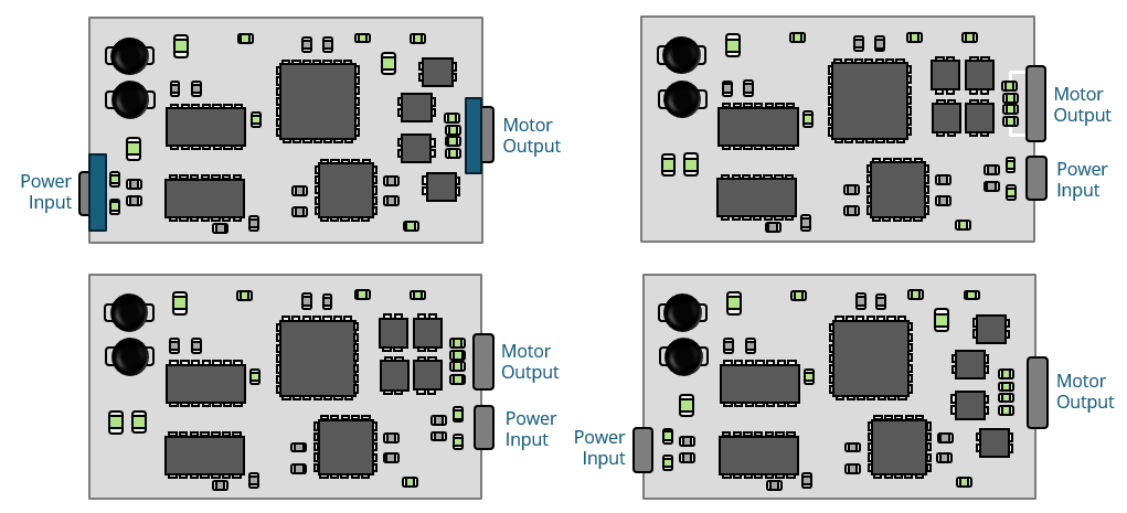
A 12-volt DC motor driver is laid out on a circuit board in a plastic enclosure that has a power input connector and a motor cable connector. To minimize EM emissions, the two connectors should be located
- over a ferrite slab
- over isolated grounds
- near each other
- on opposite sides of the board
Answer
The best answer is “c.” Modern low-voltage DC motor drivers are not major sources of EM interference. With good design practices, they can easily meet conducted and radiated emissions requirements, even when mounted in plastic enclosures. Key design features necessary to ensure compliance include having a solid ground plane and not allowing the switching circuits to be located between the external connections.
Some data sheets and application notes recommend placing the input and output connectors on opposite sides of the board. The reason often given is that it's necessary to keep the "noisy" motor currents away from the DC input where conducted emissions are measured. However, placing the connectors on opposite sides of the board basically guarantees that the switching currents will generate a common-mode voltage that drives the power input relative to the motor output. Without a metal enclosure, it's very difficult to compensate for this design mistake.
Direct coupling from the motor output connector to the power input connector is virtually never an issue when both connections are properly filtered to the common ground plane. In fact, it is not uncommon for all the external connections to be made in the same connector.
Of course, it is still necessary to employ good PCB layout practices. The switching times should be controlled, and it's important to minimize the size of the switching voltage nodes and switching current loops.
Have a comment or question regarding this solution? We'd like to hear from you. Email us at