EMC Question of the Week: August 28, 2023
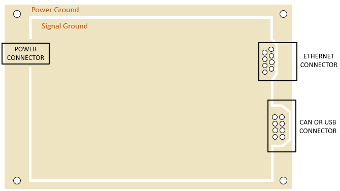
The circuit board ground layout shown in the figure is recommended for boards without a nearby chassis. This is a classic example of
- partitioning (zoning)
- decoupling
- a Faraday cage
- poor design advice
Answer
The best answer is “d.” This board locates high-speed digital circuitry between external connections. The high-speed circuitry is evidenced by the Ethernet and CAN or USB communications. Those high-speed digital connections are located on the side of the board opposite the power connector. This is bad connector placement in any design but is particularly problematic when there is no chassis to connect to.
Even in situations where the designer is forced to place connectors on opposite sides of high-speed circuitry, gapping the plane as shown in the figure creates more problems than it solves. The goal of the design is to avoid driving one cable relative to another with a high-frequency voltage. Isolating the power connector ground from the high-speed connector signal reference ground makes that goal more difficult to achieve.
Splits in a ground plane are often justified as being needed to control the flow of low-frequency current (e.g., some transient immunity currents, or the DC component of some signal currents). However, the design in the figure does not accomplish this, and in general, splitting one layer of a board into two ground planes creates more problems than it solves.
Partitioning (or zoning) generally refers to the placement of components and circuits on a board according to their function. This is a good practice, but generally does not require isolating areas of the ground plane.
Have a comment or question regarding this solution? We'd like to hear from you. Email us at