EMC Question of the Week: July 24, 2023
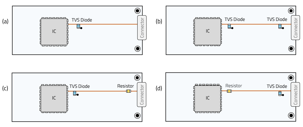
A microstrip trace connects a 5-pF CMOS input pin to an external connector pin. Which layout generally provides the best ESD protection for the IC?
- TVS diode near the IC input pin
- TVS diodes near both IC and connector pins
- TVS diode near the IC input pin and series resistor near connector
- TVS diode near the connector pin and series resistor near IC
Answer
The best answer is “d.” The TVS diode near the connector prevents transient currents from coming too far onto the board. The series resistor slows down the voltage rise at the IC input allowing the diode time to turn on before the IC sees a damaging voltage.
Without the resistor, a damage-causing voltage may appear at the IC input before the TVS diode has time to react. Two diodes on the same trace provide little additional benefit.
If the resistor is placed between the diode and the IC (as in option c), the IC sees the same voltage waveform as the diode and (as in the first three options) may be damaged before the diode turns on.
The series resistor near the IC also protects the input from field-coupled ESD transients that are often too fast for even the fastest TVS diodes. And an added benefit of the resistor is that it helps to block high-frequency currents that may be coming out of the IC pin.
Note that in many cases, the resistor alone can provide sufficient ESD protection for an IC pin. On the other hand, TVS diodes alone (without a series impedance) are unlikely to provide adequate ESD protection for a high-impedance IC input. For high-speed differential inputs, it is usually best to employ components that combine the diodes and series impedances in a single low-inductance package.
Have a comment or question regarding this solution? We'd like to hear from you. Email us at