EMC Question of the Week: June 19, 2023
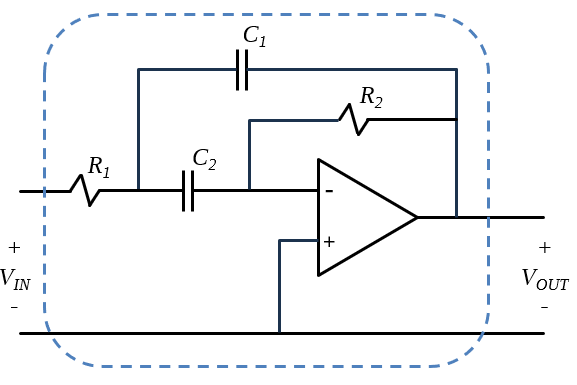
The two-port network illustrated in the attached figure is a
- low-pass filter
- high-pass filter
- band-pass filter
- band-stop filter
Answer
The best answer is “c.” The schematic in the figure shows an active band-pass filter. The lower cut-off frequency is determined by R1 and C1. The upper cut-off frequency is determined by R2 and C2.
The quickest way to answer this question is to replace the capacitors with open or short circuits to determine what happens at very low or very high frequencies, respectively. If C1 and C2 are open circuited, none of the input signal reached the output. At very high frequencies, the capacitors are essentially shorted. In this case, the output of the amplifier is fed back into the inverting input of the amplifier and again there is no signal output.
Active filters that employ high-gain amplifiers are potentially susceptible to radiated immunity problems. Small voltages coupled to the input of the amplifier that are not compensated for by the feedback can drive the amplifier outside its linear range. For this reason, care must be taken when laying out an active filter on a printed circuit board. The loop areas associated with the amplifier input and feedback must be kept small. The entire circuit should be located over a solid return plane, and the input and feedback components should lie flat over the plane.
Have a comment or question regarding this solution? We'd like to hear from you. Email us at