EMC Question of the Week: March 13, 2023
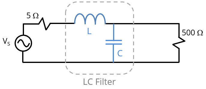
An LC low-pass filter is designed to attenuate noise from a 5-Ω source before it reaches a 500-Ω load. In order to avoid a resonance (negative insertion loss) near the cut-off frequency, the values of L and C should be chosen such that
- either (a.) or (b.)
Answer
The best answer is “d.” If we refer to as the filter impedance, Zfilter, then the filter is matched to the source when Zfilter = 5 Ω. It is matched to the load when Zfilter = 500 Ω. The cut-off frequency is . When the filter is matched to the source or the load, the insertion loss is nearly 0 dB below the cut-off frequency and begins increasing at 40 dB/decade above the cut-off frequency. There is a slight negative insertion loss near cut-off.
When Zfilter < 5 Ω, the filter is overdamped. For Zfilter << 5 Ω, the inductor doesn't contribute, and the insertion loss is the same as that of a first-order RC filter. When Zfilter > 500 Ω, the filter is also overdamped. For Zfilter >> 500 Ω, the capacitor doesn't contribute, and the insertion loss is the same as that of a first-order RL filter.
When 5 Ω < Zfilter < 500 Ω, the filter is underdamped. This creates a resonance near the cut-off frequency where the insertion loss goes negative. To maximize the effectiveness of an LC filter, without a significant spike in the insertion loss near cut-off, it is generally desirable to match the source or the load resistance (or perhaps be slightly overdamped).
Have a comment or question regarding this solution? We'd like to hear from you. Email us at