EMC Question of the Week: November 28, 2022
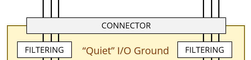
When a circuit board layout has a "quiet I/O ground" under the connector, that ground should usually be connected to other grounds on the board
- through resistors
- through ferrites
- at a single point
- none of the above
Answer
The best answer is “d.” Designating the area of a circuit board's ground plane under a connector as a "quiet" ground is fine. In fact, when a board has one connector (or all connectors along the same edge), the ground plane under the connector is the "EMC ground" for that board. High-frequency currents should not be returned on that plane parallel to the edge of the board. If the board is mounted to a metal chassis, the connection to the chassis should be near the connector (preferably on both sides).
The best way to connect the "quiet" ground to the signal return grounds on the board is usually to make them part of the same plane as illustrated in the figure below (right). Some older texts and application notes advocate isolating the "quiet" ground from the "noisy" current-return ground by splitting the plane as illustrated in the figure below (left). This is generally a terrible idea. It reduces the effectiveness of the filtering and encourages the development of a high-frequency voltage across the gap that puts a common-mode voltage on the I/O. (It also violates the general design rule that "signal traces should never cross a gap in the return plane.)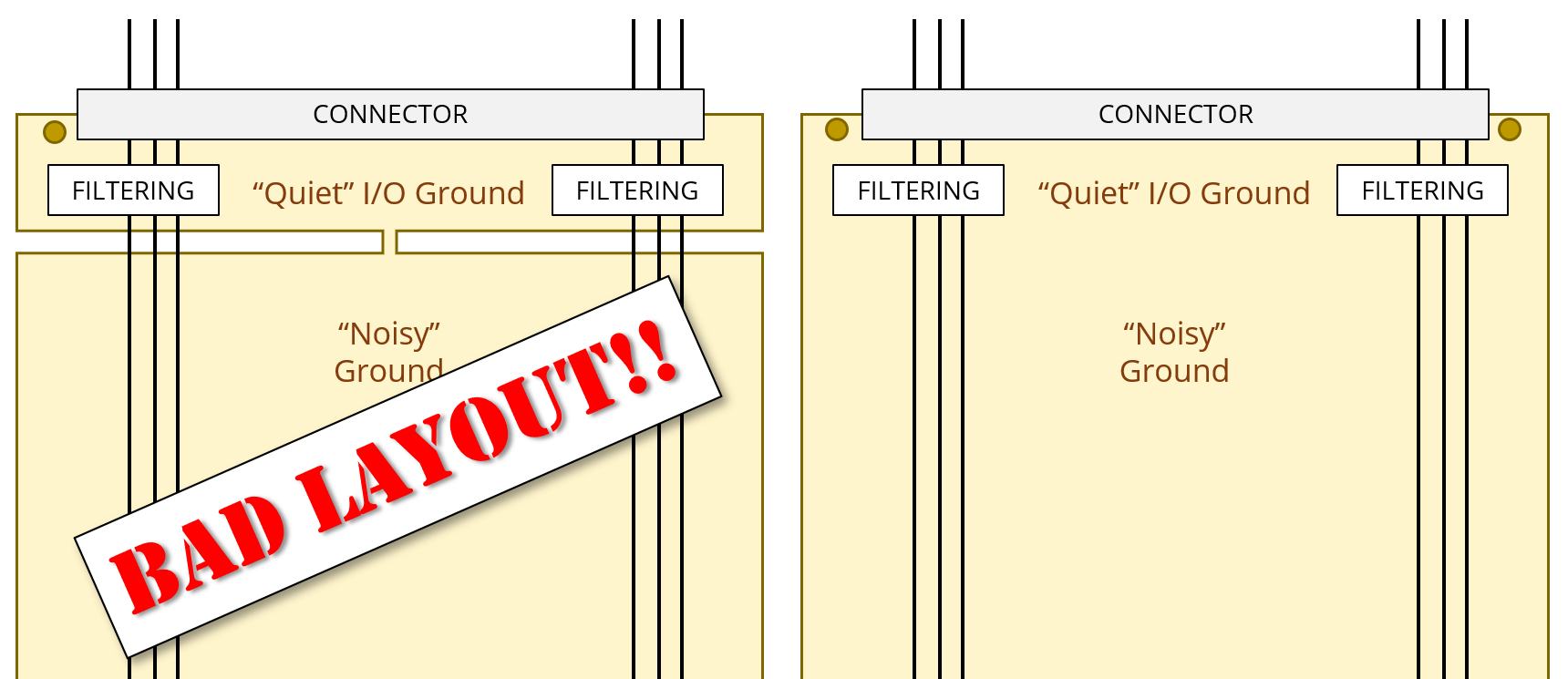
In situations where a chassis ground must be isolated from the signal return ground for safety reasons, the "quiet" I/O ground would always connect to the chassis (if it's nearby). The I/O ground could not have a low-frequency connection to the signal return ground at any point on the board. In this case, the signal return ground should generally extend under the I/O ground and the two grounds should be well-connected at high frequencies through capacitors.
Of course, there are exceptions to every EMC design rule; and the general guidance above may not be the best option in every situation. Nevertheless, it's safe to say that the layout on the left side of the figure is never a good option. It provides no low-frequency isolation when required for safety reasons and it introduces an unwelcome impedance in the return path of high-frequency signal and noise currents.
Note: The idea of creating a "quiet ground" connected to the rest of the board ground through a "bridge" of copper originated around 25 years ago when many people assumed high-frequency currents spread out on a ground plane the way low-frequency currents do. The basic idea was to contain the high-frequency currents and keep them away from the connector. Today, it's well understood that currents at MHz frequencies and higher take the path of least inductance. It's much more effective to control high frequency currents through routing rather than attempting to restrict their return path.
Have a comment or question regarding this solution? We'd like to hear from you. Email us at