EMC Question of the Week: June 20, 2022

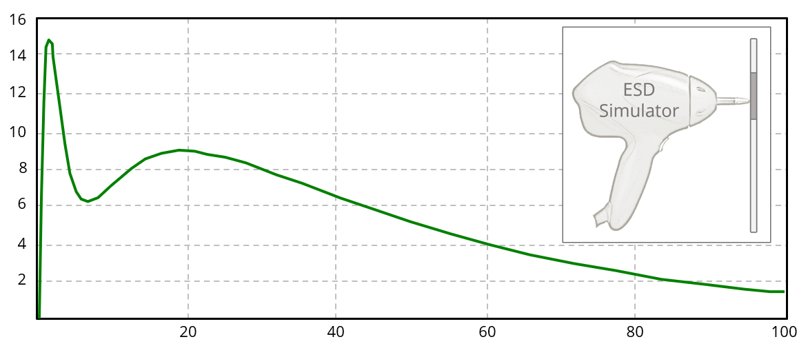
The often-cited contact discharge waveform in IEC 61000-4-2 (shown here) plots the
- voltage in kV vs. time in μs
- voltage in kV vs. time in ns
- current in kA vs. time in μs
- current in A vs. time in ns
Answer
The correct answer is “d.” The waveform plots the current in amperes resulting from a 4 kV discharge flowing through a target with less than 2.1 Ω of DC resistance embedded in a metal plane. There is an initial spike in the waveform as current flows across the plane returning to the simulator as displacement current. After about 10 ns, most of the current is returning through the simulator's ground strap. The waveform specified in MIL-STD-461G is similar, except the discharge voltage and the waveform current are doubled, so the same simulator can be used for testing to either standard.
The current waveform resulting from a discharge to an actual device under test is generally very different from the calibration waveform. There can be several quick spikes as different metal surfaces in the DUT become charged. Also, the rise and fall times associated with the current returning in the ground strap depend on the inductance and resistance of that path for a given test setup.
Have a comment or question regarding this solution? We'd like to hear from you. Email us at
