EMC Question of the Week: August 30, 2021

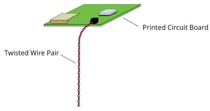
A circuit board sends a signal down an unshielded twisted wire pair as illustrated in the figure. The differential-mode characteristic impedance of the wire pair is 100 Ω. The common-mode characteristic impedance
- is less than 100 Ω
- is greater than 100 Ω
- could be more or less than 100 Ω
- is undefined
Answer
The best answer is “d.” Characteristic impedance is a ratio of the voltage to the current associated with a single mode propagating on a transmission line. While it is well defined for guided wave structures with uniform cross-sections, it cannot be applied to very non-uniform or radiating structures.
For an unshielded twisted wire pair, we can easily define and measure the common-mode current. We can also define a common-mode voltage that drives the common-mode current at a given location. The ratio of the common-mode voltage to the common-mode current at that location is the input impedance for that structure. Unlike a characteristic impedance, the input impedance is generally a function of both location and frequency. For a resonant cable structure in a semi-anechoic environment, the common-mode input impedance can be as low as 36 Ω. For non-resonant structures, the input impedance is complex and can have magnitudes of several hundred kΩ or higher.
Note that common-mode propagation on an unshielded twisted wire pair DOES have a defined characteristic impedance when extended horizontally a fixed height over a ground plane (assuming the height is very short relative to a wavelength). In this case the characteristic impedance is a function of the effective diameter of the wire pair and the height above the plane. It is typically between 150 and 250 Ω at a height of 5 cm but can be greater than 400 Ω at heights of a meter or more.
Have a comment or question regarding this solution? We'd like to hear from you. Email us at
