EMC Question of the Week: July 12, 2021
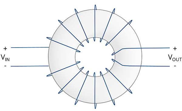
A ferrite toroid with signal wires wrapped in the direction indicated in the figure, serves as
- a common-mode choke
- a differential-mode choke
- an ideal transformer
- a DC block
Answer
The correct answer is “a.” Common-mode currents flowing from the input to the output induce magnetic flux in the toroid causing the common-mode currents to experience a high-frequency impedance. Differential-mode currents flowing in opposite directions on each wire (e.g. right-to-left on the top wire and left-to-right on the bottom wire) induce opposing fluxes in the toroid that largely cancel each other. For that reason, the impedance presented to a differential-mode signal is much lower.
From the viewpoint of magnetic flux circulating in the toroid, both windings are in the same direction. For example, flux circulating clockwise in the toroid as viewed in the figure, "sees" both windings rotating counter-clockwise around the toroid's cross-section.
If the rotation of one of the windings were reversed, the device would impede differential-mode currents while passing common-mode currents (essentially, a differential-mode choke). If we connected this device differently, so that VIN were across the two ends of the top wire and VOUT were across the two ends of the bottom wire, we would have a 1:1 transformer (which would also function as a DC block and a common-mode choke).
Have a comment or question regarding this solution? We'd like to hear from you. Email us at