EMC Question of the Week: July 6, 2020
A single-ended 10-MHz digital clock propagating on a circuit board (75-Ω microstrip line) passes through a connector where it transitions to a 100-Ω twisted wire pair. If the peak-to-peak differential voltage on the twisted wire pair is 3.3 V, what is the common-mode voltage that drives the wire pair relative to the board at 30 MHz?
- 250 mV
- 25 mV
- 25 μV
- < 1 μV
Answer
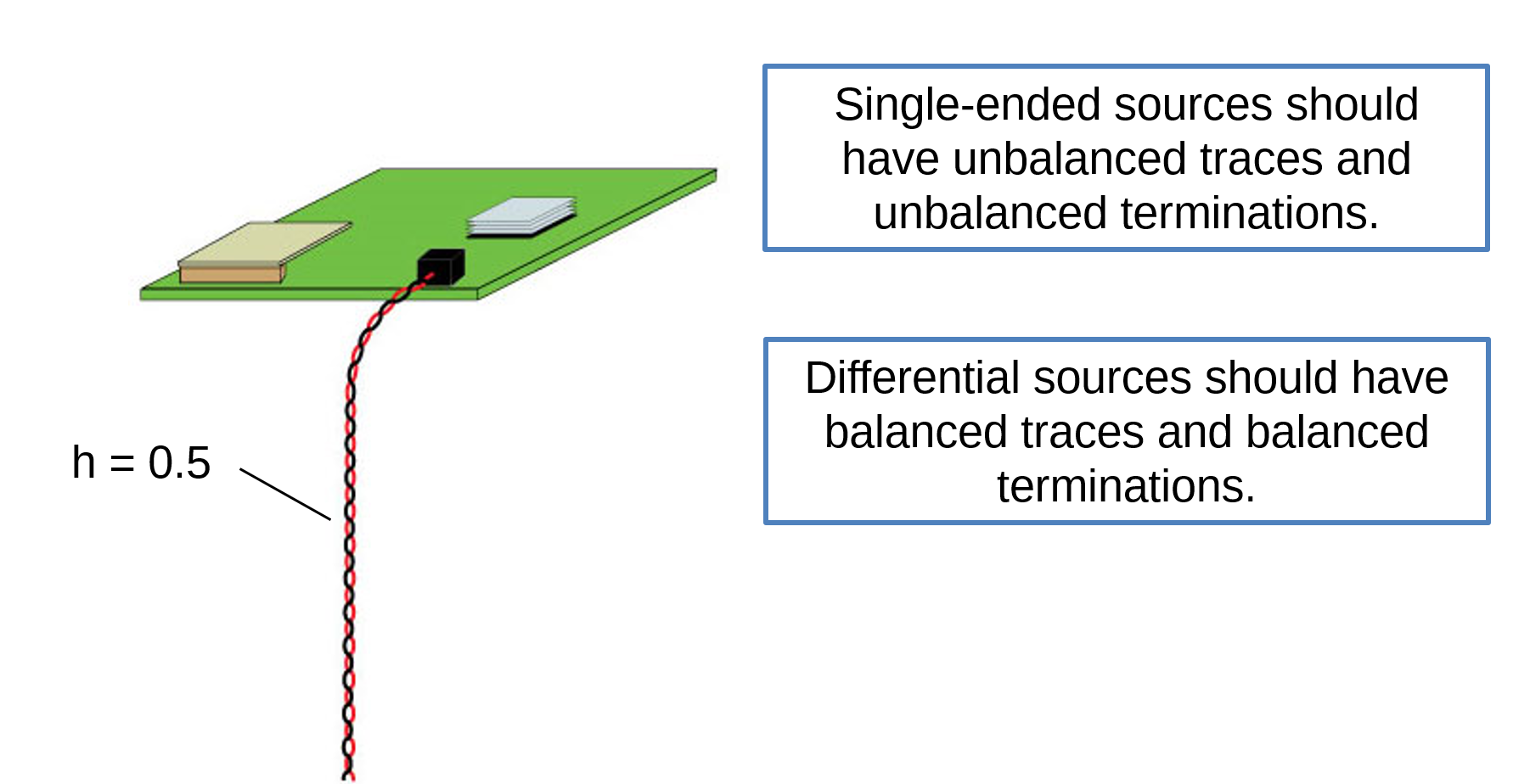
The best answer is "a". First, we must calculate the amplitude of the signal harmonic at 30 MHz. The first harmonic of a clock signal has an rms amplitude that is 0.45 times the peak-to-peak signal voltage. In this case, that's about 1.5 V. The third harmonic has an amplitude that is one third of this or 0.5 V. The transition from an unbalanced microstrip trace to a balanced twisted wire pair converts approximately half of the differential-mode voltage to a common-mode voltage that drives the cable relative to the board. In this case, half of 0.5 V is 0.25 V (or 250 mV).
Note that the mismatch in the impedance does not affect the mode conversion. Impedance mismatches cause reflections that can affect the signal amplitude, but in this case, the signal amplitude on the wire pair was given.
Although the radiated emissions from this configuration will depend on the size of the board and the cable configuration, the worst-case emissions from a large board (or a small board with other cables attached) is about 60 dB above the FCC and CISPR radiated emissions limit at 30 MHz. Generally speaking, a single-ended clocks at 10 MHz and higher should not be transmitted on twisted wire pairs or other balanced transmission lines.
Have a comment or question regarding this solution? We'd like to hear from you. Email us at