Faraday's Law for EMC Engineers
In the early 1800s, an Englishman named Michael Faraday discovered that a time-varying magnetic field was capable of producing a voltage in an electric circuit. This discovery was an important step toward the development of electromagnetic theory, and Faraday's Law in its various forms continues to be one of the more important equations for EMC engineers today.
Quiz Question
The algebraic sum of all the voltages around any closed path in a circuit equals zero.
- true
- false
Electrical engineers will recognize the sentence above as a statement of Kirchhoff's Voltage Law (KVL). Nevertheless, if we are talking about real implementations of circuits, the correct answer is b.) false. KVL is a very useful concept and a cornerstone of circuit theory. Unfortunately, circuit theory doesn't always apply to real implementations of circuits. Circuits (and everything else in the known universe) comply with Maxwell's equations. However, it's a bit tedious to try to solve Maxwell's 3-dimensional, vector field equations every time we want to analyze a circuit. All of circuit theory can be derived from Maxwell's equations by making certain simplifying assumptions about the nature of circuits.
For example, let's take a closer look at Faraday's Law, which is one of Maxwell's equations,
. (1)
The equation basically says that if we were to define a closed path in any arbitrary location and sum the product of the electric field and length around the loop, the total voltage obtained would be equal to the time-rate-of-change of the magnetic flux passing through that closed path. This equation always holds no matter how or where we define the path, so let's apply Faraday's Law to the circuit in Figure 1.
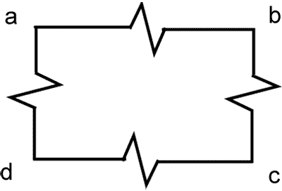
Figure 1. Circuit with 4 resistors.
The circuit consists of four resistors connected in a loop using perfectly conducting wire. We can choose our path to be anywhere, so let's define it to be along the center of the wire and through the middle of each resistor. The electric field inside a perfectly conducting wire must be zero; therefore, in this case, Faraday's Law (1) can be simplified to,
. (2)
By definition, is the voltage between a and b, or in this example, the voltage across the top resistor, VA. The other terms in (2) are the other voltages dropped in the circuit. Therefore (2) can be written,
. (3)
If there are no time-varying quantities (i.e., the magnetic flux density is constant, and the circuit doesn't move, then the right-hand side of (3) is zero, and Faraday's Law can be written as,
. (4)
This is KVL for this circuit.
However, if the flux and/or the circuit change with time, then the right-hand side of (3) may not be zero, and KVL does not apply. The term on the right-hand side of (3) represents the time-rate-of-change of the total magnetic flux passing through the circuit. The total flux is the integral of the flux density over the circuit loop area,
. (5)
Therefore, for circuit loops of arbitrary shape and size consisting of small components connected by perfectly conducting wire, Faraday's Law tells us that,
. (6)
where Ψ is the total magnetic flux passing through the loop made by the circuit. For convenience, we will refer to the sum of all voltages dropped across components in a loop as VLOOP.
Example 1: High Impedance Loop in a Uniform H-Field
Consider the circuit below consisting of two resistors connected with wire forming a 5-cm by 3-cm loop. If the circuit is located in a 150 kHz, 2.0 A/m magnetic field, determine the voltage induced across the 10-ohm resistor. The direction of the magnetic field is perpendicular to the plane of the paper (i.e., maximum coupling).
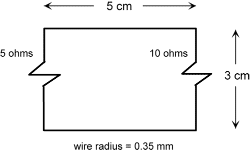
Figure 2. Circuit in a low-frequency magnetic field.
The sum of the voltages across the two resistors in this circuit will equal the derivative of the total magnetic flux coupling the loop,
. (7)
Since the field in the loop is uniform, the total flux, Ψ, is equal to the flux density, B, times the loop area. The loop is in free space, so the flux density, B, is equal to μoH, and (7) can be expressed as,
. (8)
The voltage dropped across the 10-ohm resistor is a fraction of the total voltage dropped across all components in the loop. Using voltage division, we can express the voltage dropped across the 10-ohm resistor as,
. (9)
Suppose the circuit in Example 1 had no resistors. If it were a perfectly conducting loop of wire, the E-field would have to be zero everywhere inside the wire, and the value of would be zero. According to Faraday's Law,
. (10)
In other words, the net time-varying flux passing through a perfectly conducting loop must always equal zero. How can this be true?
If a perfectly conducting loop is placed in a time-varying magnetic field, current induced in the loop creates an opposing magnetic field such that the total magnetic flux passing through the loop is always exactly zero,
. (11)
The magnitude of the induced current is,
. (12)
If the wire loop had finite resistance, or if there were resistors in the loop, the current in the loop would be,
(13)
where RLOOP is the total loop resistance, and LLOOP is the total loop inductance. The voltage dropped across a small lumped resistance, R1, in the loop would be,
. (14)
Example 2: Low Impedance Loop in a Uniform H-Field
Consider the circuit below consisting of a 2-ohm resistor connected to a 5-cm by 3-cm loop of wire. If the circuit is located in an 80-MHz, 500-μA/m magnetic field, determine the voltage induced across the 2-ohm resistor. The direction of the magnetic field is perpendicular to the plane of the paper (i.e., maximum coupling).
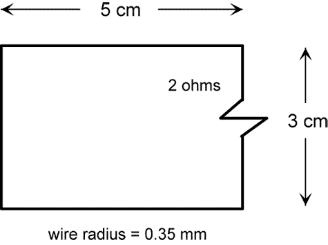
Figure 3. Circuit in a high-frequency magnetic field.
Using our equation for the inductance of a rectangular loop of wire, we can show that the inductance of this loop is 125 nH. At 80 MHz, the inductive reactance of the loop is then ωL = 63 ohms.
Clearly, the loop inductance will limit the amount of current induced and, therefore, the amount of voltage that can appear across the resistor. However, we can still calculate the quantity VLOOP as follows,
. (15)
The voltage dropped across the 2-ohm resistor can then be determined as a fraction of VLOOP using Equation (14),
. (16)