Design for Automotive EMC Compliance
Description
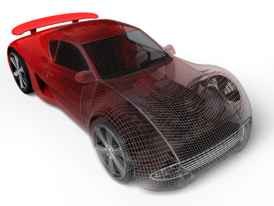
Automobiles are complex electronic systems containing dozens of microprocessors, hundreds of sensors and actuators, and a variety of RF transmitters and receivers. Keeping track of all possible interactions that might result in an electromagnetic interference problem can be a formidable task. Nevertheless, with a proper design strategy, compliance with automotive electromagnetic compatibility requirements can be relatively straightforward.
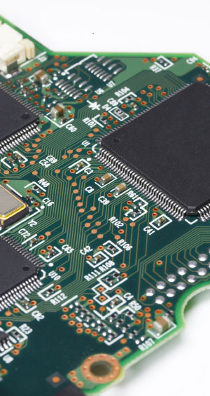
First-pass compliance with automotive EMC requirements starts with circuit board layout. Printed circuit board layout is often the single most important factor affecting the electromagnetic compatibility of electronic systems. Boards that are auto-routed or laid out according to a list of “design rules” rarely meet electromagnetic compatibility requirements on the first pass, and the products using these boards are more likely to require expensive EMC “fixes” such as ferrites on cables and shielded enclosures. Taking the time to ensure that components are properly placed and traces are optimally routed will generally result in products that meet all electromagnetic compatibility and signal integrity requirements on time and on budget.
Automotive components are subjected to a unique set of EMC tests that can be difficult to comply with unless specific design precautions are implemented early in a product's development. These EMC tests are readily modeled, and the models can be used to guide the development of the component in a manner that will guarantee EMC compliance. For example, radiated emissions failures at frequencies up to a few hundred megahertz are typically the result of driving a wire harness with a common-mode voltage relative to system ground. This voltage is independent of the harness length or routing and can be determined using relatively simple models. Simple models also exist to predict the worst-case result of the other EMC compliance tests, including BCI, EFT, ESD, and conducted emissions tests.
Of course, decisions related to wire harness design and routing can also have a profound effect on a vehicle's electromagnetic compatibility. Even if all of the automotive components meet their EMC requirements, interference problems can arise due to poor grounding and signaling decisions at the vehicle level. This course provides overall strategies for vehicle-level design, including component characterization for vehicle-level modeling and system interactions that must be accounted for early in the automotive design process.
Overall, this course stresses the fundamental concepts and tools that automotive electronics engineers can utilize to avoid electromagnetic compatibility and signal integrity problems. Students completing the course will be able to make good decisions regarding board layout and automotive system design for EMC. They will also be introduced to tools and techniques for quickly reviewing automotive designs in order to flag potential problems well before the first hardware is built and tested.
Continuing Education Credit: 1.5 CEUs, 15 PDHs
Course Outline
Part 1 - Important Fundamental Concepts
- Introduction
- Overview of Automotive Components and Systems
- Automotive EMC Requirements
- Impact of Early EMC Design on Product Compliance and Cost
- Design for Compliance vs. Design to Fail-and-Fix
- Review of EMC Fundamentals
- Tracing Current Paths / Concept of Least Impedance
- EM Coupling Mechanisms
- Transition Time Control
- Transmission Lines
- Identifying Unintentional Antennas/Ports
- Essential Elements of an Antenna
- The Wire Harness
- The Chassis/Enclosure
- Noise Sources and Coupling Mechanisms
- Common Automotive Noise Sources
- Conducted Emissions
- Radiated Emissions
- Radiated Immunity
- ESD and Transient Susceptibility
- Grounding
- Ground vs. Signal Return
- Ground Structures and Grounding Conductors
- Utilizing Vehicle Ground
- Ground in Mixed-Signal Environments
- Filtering
- Insertion Loss
- First-Order Filters
- Second-Order Filters
- Power Input Filters
- Component Parasitics and Layout
- Shielding
- Electric Field Shielding
- Magnetic Field Shielding
- Shielding to Reduce Radiated Emissions
- Cable Shielding
Part 2 - Design Tools and Techniques
- Strategies for PCB Layout
- Design Guidelines (Good and Bad)
- Optimizing Component Placement
- Stack-up and Routing Priorities
- Common Problems that are Easily Avoided
- Strategies for Vehicle Layout
- Design Guidelines (Good and Bad)
- Optimizing Component Placement
- Wire Harness Design and Routing
- Common Problems that are Easily Avoided
- Key Design Considerations
- For Radiated Emissions Tests
- For Conducted Emissions Tests
- For BCI and Radiated Susceptibility
- For ESD and Transient Tests
- Design Review Steps and Examples
- Identifying Sources/Victims
- Identifying Antennas/Ports
- Applying Design Guidelines/Criteria
- Tools of the Trade
- Schematic and Board Layout Tools
- Circuit Solvers
- Field Solvers
- AI and Design Rule Checkers
- Maximum Emissions/Coupling Calculators
- Specific Design Examples
- Engine Control Module
- Body Control Module
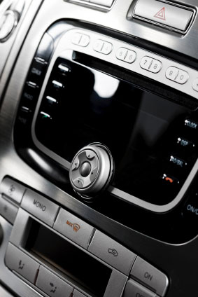
- Infotainment System
- Low-Voltage Motor Driver
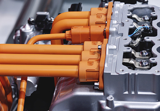
- High-Voltage Inverter
- Others Provided by Class
- Course Summary
- Review of Key Concepts
- Resources for Automotive EMC Engineers
Course Instructor

Dr. Todd H. Hubing is a Professor Emeritus of Electrical and Computer Engineering at Clemson University and former Director of the Clemson Vehicular Electronics Laboratory. He has contributed to the development and analysis of hundreds of automotive electronic components and systems. At Clemson, he and his students were able to guarantee that the products they reviewed would meet all automotive EMC requirements on the first test pass. They were able to make this guarantee by applying the concepts outlined in this course, along with simple tools to calculate the maximum possible coupling from various components and circuits. Instead of applying general design guidelines that may or may not be helpful in a given situation, this approach makes it possible to identify exactly what is necessary to ensure product compliance.