Power Bus Decoupling Guidelines for Printed Circuit Boards without Power Planes
Applicable to:
1- or 2-sided boards or multi-layer boards that do not employ planes for power distribution
General Guidelines
-
Provide at least one "local" decoupling capacitor for each active device and at least one larger "bulk" decoupling capacitor for each voltage distributed on the board.
-
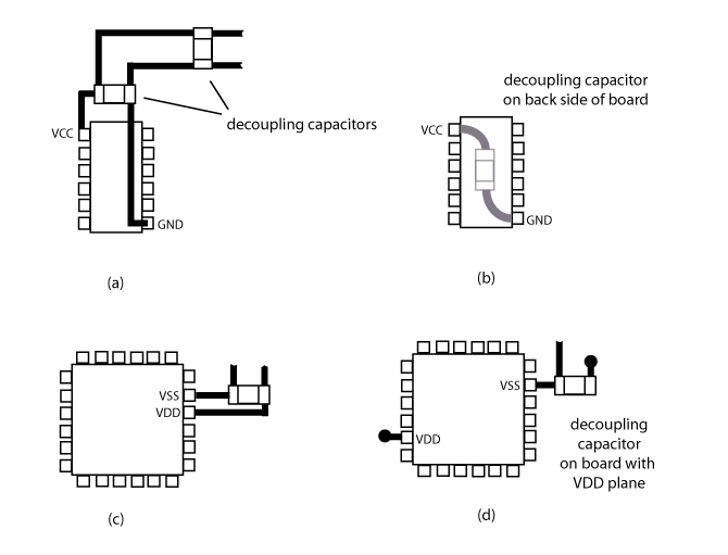
Local decoupling capacitors should be connected between the voltage and ground pins of the active device. the area of the loop formed by the capacitor/device connection should be minimized.
-
Local decoupling capacitors typically have nominal values of 0.001, 0.01 or 0.047 microfarads. Some active devices may require several local decoupling capacitors in order to respond to a sudden demand for current.
-
Bulk decoupling capacitors should be located near the point where a voltage comes on to the board. If the voltage is generated on the board, the bulk decoupling should be near the location where it is generated.
-
Bulk decoupling capacitors should be sized to meet the transient current needs of the entire board. Typically, bulk decoupling capacitors have values equal to 1 - 10 times the sum of the values of the local decoupling capacitors connected to the same bus.
-
As a general rule, two local decoupling capacitors with the same nominal value are better than one capacitor with twice the nominal value. Two capacitors have a lower overall connection inductance [1] and provide better high-frequency filtering to the rest of the power bus [2].
Examples
The figure below shows various examples of good local decoupling capacitor connections to boards without power planes.

References
[1] C. R. Paul, "Effectiveness of Multiple Decoupling Capacitors," IEEE Trans. on Electromagnetic Compatibility, vol. 34, no. 2, May 1992, pp. 130-133.
[2] T. Zeeff, T. Hubing, T. Van Doren and D. Pommerenke, "Analysis of Simple Two-Capacitor Low-Pass Filters," IEEE Trans. on Electromagnetic Compatibility, vol. 45, no. 4, Nov. 2003.
