Estimating the Connection Inductance of a Decoupling Capacitor
What many people refer to as the equivalent series inductance (ESL) of a capacitor is the inductance of the loop formed by current that flows in one terminal and out the other terminal. For SMT capacitors, it is more accurate to call this the connection inductance, since it depends much more on the geometry of the connection than on the internal construction of the capacitor. Connection inductance is the most important factor affecting a decoupling capacitor's ability to supply current at high frequencies. By estimating the connection inductance, the effective bandwidth of a decoupling strategy can be determined. The following outlines a method by which the connection inductance of a variety of decoupling capacitors can be estimated.
Step 1: Identify the Loop
The first step in estimating the inductance of a decoupling capacitor is to identify the decoupling current loop. Two cases will be considered, decoupling capacitors on boards with power routed on traces, and decoupling capacitors on boards with power and return planes.
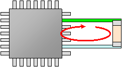
A. Geometries where power is routed on traces
The current loop will consist of the path between the decoupling capacitor and the device that draws charge from the capacitor. In the figure shown below, the current path is shown in red.
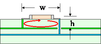
B. Decoupling capacitors connected to power planes
The current loop in this configuration will start at the decoupling capacitor, go through a via to one of the power planes, then from one power plane to the other, and finally through a via back to the capacitor. The impedance of the path between the power and return planes, Zboard, is not normally considered to be part of the connection inductance. Zboard can be calculated independent of the inductance of the portion of the loop above the planes. The impedance of the connection to the planes is then given by, Zconn = jωL + Zboard, where L is the inductance of the current path above the power planes. This path is shown in red in the figure below.
Step 2: Identify an Equivalent Geometry
To estimate the inductance for decoupling capacitors, the inductance of an equivalent geometry will be used. This simplification will allow us to use simple closed-form expressions to calculate the inductance.
A. Decoupling capacitors where power is routed on traces
Rectangular Loop
If the decoupling current loop is short (w<5h), then use the closed-form expression for a rectangular loop to calculate the inductance.
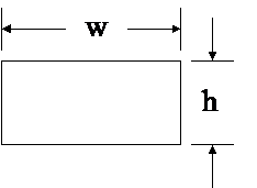
Long Rectangular Loop (w>5h)
If the decoupling current loop is long (w>5h), then use the expression for the inductance per unit length of two wires and multiply by the length of the loop (w) to calculate the inductance.
B. Decoupling capacitors connected to power planes
Rectangular Loop above a Plane
If the decoupling loop is short (w<5h), use the closed-form expression for a rectangular loop with the parameter 'h' equal to 2h1, and then divide the calculated inductance in half. This inductance will be the inductance Labove.
Calculator: Inductance of a Rectangular Loop

Long Rectangular Loop above a Plane (w>5h)
If the decoupling current loop is long (w>5h), use the expression for the inductance per unit length of a wire above a ground plane and multiply by the length of the loop (w). This inductance will be the inductance Labove.
Calculator: Inductance of Wire Above Return Plane
Step 3: Estimating the parameters of the closed-form inductance calculations
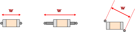
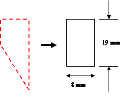
A. Estimating loop width 'w'
The loop width 'w' is the distance over which the current follows through the capacitor. A few examples are shown below.
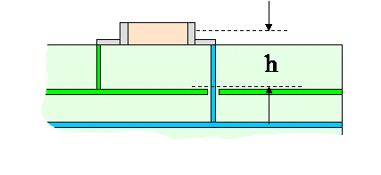
B. Estimating loop height 'h'
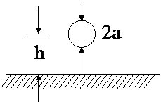
The height of the loop 'h' for a capacitor attached to power planes would be approximately half the height of the decoupling capacitor plus the distance between the capacitor and the closest power plane.
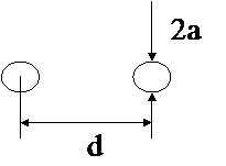
C. Estimating wire radius 'a'
The equivalent wire radius of a decoupling capacitor or flat trace can be estimated as 1/4th the width of the capacitor package or trace. Of course, most connections consist of vias, traces, pads and capacitor packages that have different equivalent wire radii. A worst-case estimate of the connection inductance is obtained by using the smallest equivalent radius.
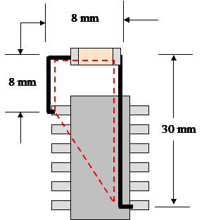
Example 1: PCB Without Power Planes
Calculate the connection inductance for the capacitor connected to a device through traces as shown below. The traces are 1 mm wide. All other dimensions are shown below.
Solution:
The connection inductance can be approximated with the use of the rectangular loop equation (Calculator: Inductance of a Rectangular Loop). The length and width of the rectangle itself is estimated from the current path shown as a red dashed line in the figure above. The length of the equivalent rectangular loop is estimated to be 8 mm plus half of the length of the triangular portion of the current loop (22 mm/2 = 11 mm). The equivalent radius of the wire, a, is 1/4th of the trace width.
Ans. Lconn = 29 nH ≈ 30 nH

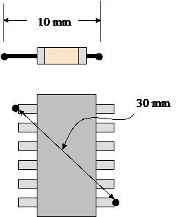
Example 2: Decoupling Capacitors Connected to Power Planes
Calculate the connection inductance between a capacitor and a device assuming both are connected to power and return planes. The via diameters are 2 mm and the dip package and capacitor are approximately 3 mm above the surface of the power and return plane pair. Neglect the impedance through the power planes.
Solution:
Inductance of the capacitor connection
To calculate the inductance of the decoupling capacitor, Lcap, the formula for the inductance of a 'Rectangular loop above a plane' will be used (Calculator: Inductance of a Rectangular Loop). The length and width of the equivalent loop for the decoupling capacitor are 10 mm and 3 mm respectively. The equivalent radius of the loop will be the 1 mm radius of the vias.
Lcap = 3.6 nH ≈ 4 nH Inductance of the DIP package connection
The inductance of the DIP package connection to the power planes, LDIP, will be calculated with the 'long rectangular loop above a plane' formula (Calculator: Inductance of Wire Above Return Plane). The length of the loop will be 30 mm, the height of the loop will be 3 mm, and the equivalent radius will be approximated as 0.1 mm.
LDIP = 24.6 nH ≈ 25 nH
Lconn = Lcap + LDIP = 28.2 nH ≈ 28 nH
Example 3: The Inductance of a Decoupling Capacitor Loop
The figure below shows several decoupling capacitor pads on a PCB. The distance between the top layer and the power/return plane pair was 0.02"; all other measurements are shown on the figure. The inductance of the following pad designs was measured with a network analyzer and the results are summarized below.
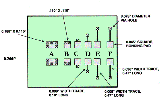
| Case | L(nH) |
| A | 0.61 |
| B | 1.32 |
| C | 2.00 |
| D | 7.11 |
| E | 15.7 |
| F | 10.3 |
Inductance of Case C:
Method 1: Using the 'rectangular loop above a plane' algorithm
ANS: L=3.1 nH ≈ 3 nH
Method 2: Using the 'long rectangular loop above a plane' algorithm
ANS: L=0.75 nH ≈ 1 nH
(Note: Method 2 ignores the inductance due to the portion of the magnetic flux wrapping the vias. This is a reasonable estimate of the inductance due to the flux wrapping the capacitor body only. Flux wrapping the capacitor body dominates in Case A.)
Inductance of Case E:
Method: Using the 'long rectangular loop above a plane' algorithm once for the traces routed to the via, and again for the pad and capacitor package portion of the loop.
Contribution to loop inductance from the traces:
ANS: Lt=15.24 nH ≈ 15 nH
Contribution to the loop inductance from the pad and capacitor package:
ANS: Lp/c = 0.76 nH ≈ 1 nH