Electric-Field Coupling
Electric field coupling (also called capacitive coupling) occurs when energy is coupled from one circuit to another through an electric field. As we shall see, this is most likely to happen when the impedance of the source circuit is high.
Consider the two circuits sharing a common return plane shown in Fig. 1. If the return plane had zero resistance, the common impedance coupling would be zero. However, it is also possible for coupling to occur between the two circuits due to the electric field lines that start on one signal wire and terminate on the other. For example, if one of the signal voltages is +1 volt and the other is 0 volts, then the potential difference between the two signal wires results in electric field lines that start on the +1-volt wire and terminate on the 0-volt wire. Schematically, this can be represented by a capacitor between the two signal wires.
Of course, there are other electric field lines that start on the +1-volt wire and terminate on the 0-volt plane. This can be represented by a capacitance between the wire and the plane. A schematic representation of the two circuits in Fig. 1 that includes the electric field coupling capacitances is shown in Fig. 2.
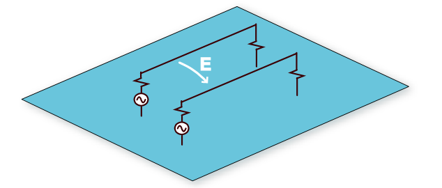
Fig. 1: Two circuits above a signal return plane.
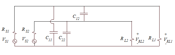
Fig. 2: Schematic representation of the circuits in Fig. 1 including capacitive coupling paths.
In this case, the capacitance between the wires, C12, is readily calculated using the formula for the capacitance between two wires, and the capacitances C11 and C22 can be calculated using the formula for the capacitance of a wire above a ground plane. Once the capacitances have been determined and values have been assigned to all the elements in Fig. 2, the crosstalk due to electric field coupling can be calculated using the same basic formula used for common impedance coupling,
. (1)
If we try to find the exact solution, the procedure for analyzing this circuit with 9 elements can be time-consuming. However, if we redraw the circuit and take advantage of the relative size of some of the impedances, we can greatly simplify the analysis.
First, let’s redraw the circuit in Fig. 2 as shown in Fig. 3. By putting Circuit 1 on the left side of the schematic and Circuit 2 on the right side, the important coupling, C12, is clearer. Also, it is helpful to recognize that the impedances of the self-capacitances C11 and C22 are almost always much higher than the load impedances that they are in parallel with. If this were not true, the signal reaching the load would be significantly attenuated. Therefore, we can usually neglect C11 and C22 when solving the circuit in Fig. 3.
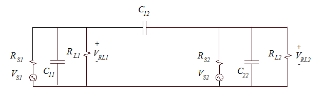
Fig. 3: More intuitive schematic representation of the circuits in Fig. 1.
To calculate the crosstalk in Circuit 2 due to the signals in Circuit 1, we set VS2 = 0 and determine the ratio VRL2/VRL1. If the coupling is relatively weak (i.e., if the coupling is not loading down the source circuit), then the impedance of C12 is large relative to the impedances in Circuit 1. This means the value of VRL1 is independent of the Circuit 2 parameters, and the circuit can be represented in the simple form shown in Fig. 4.
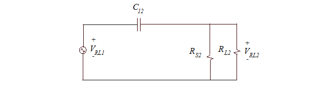
Fig. 4: An even simpler representation of the circuits in Fig. 1.
Now the circuit is relatively easy to solve. The crosstalk can be expressed as,
. (2)
Example 5-1: Calculating the crosstalk between two 150-ohm circuits
For the circuits in Figures 1 and 2, assume the signal wires are 4.0 mm above the conducting plane and 16 cm long. Assume the wire radius is 0.8 mm and the spacing between the wires is 3.0 mm. Let RS1 = RS2 = 10 ohms and RL1 = RL2 = 150 ohms. Calculate the crosstalk due to electric field coupling between these circuits at 50 MHz.
We start by determining the capacitances C11, C22 and C12. The capacitance of each wire above the plane is approximately,
. (3)
The capacitance between the two wires is approximately,
. (4)
The impedance of C11 and C22 at 50 MHz is |1/jωC| = 800 ohms. Since this is much higher than the 150-ohm circuit impedance, we can neglect these capacitances. The impedance of the coupling capacitance is |1/jωC| = 890 ohms. This is also much greater than the circuit impedances, therefore we can use Equation (2) to calculate the crosstalk,
. (5)
It is helpful to note how changing the various circuit parameters would have changed the coupling in this case. For example, doubling the frequency would have doubled the crosstalk (i.e., at 100 MHz, the calculated crosstalk would be -34 dB). For the weak coupling case, the electric field coupling is proportional to the frequency.
Doubling the source resistance of the victim circuit would also have doubled the crosstalk in this example. Note that the parallel combination of the source and load resistances was almost equal to the source resistance. In this example, doubling the load resistance would have little effect on the crosstalk, since it is the parallel combination of the source and load resistances in the victim circuit that is important.
The other important parameter in this example is the mutual capacitance, C12. Reducing the value of C12 would reduce the crosstalk proportionally. Moving the wires farther apart is one way to reduce the value of C12. However, it is important to note that merely doubling the distance between the wires is not sufficient to reduce C12 by a factor of 2. The inverse hyperbolic cosine function behaves like a logarithmic function when the wire separation is greater than the wire diameter. In this case, doubling the distance between the wires (from 3.0 mm to 6.0 mm) would have changed the value of C12 from 3.6 pF to 2.2 pF. This would have reduced the crosstalk by only about 4 dB.