Introduction to EMC Regulations and Testing
Virtually every country in the world regulates the electromagnetic compatibility of electronic products marketed or sold within its borders. Organizations such as the International Electrotechnical Commission (IEC) and the International Organization for Standardization (ISO) develop and maintain standards and test procedures for electronic products. Professional trade organizations like the IEEE and SAE also develop EMC standards.
The specific EMC requirements that apply to any given product depend on the product’s function, application, and market. EMC regulations can vary significantly from one country to another or from one industry to another. For example, in the U.S., most commercial computer equipment is subject to conducted and radiated emissions requirements but has no immunity requirements. Medical devices in the U.S. are generally subject to both emissions and immunity requirements, while automotive electronics are mostly exempt from federal EMC requirements. In Europe, on the other hand, nearly all electronic devices are subject to some form of EMC requirement.
In addition, many companies have their own EMC test requirements to ensure their products will perform reliably in the field, as well as comply with all applicable legal requirements. Products used by the military are typically subject to military EMC standards that, in some cases, can be considerably more stringent than commercial EMC requirements.
EMC tests are generally divided into two categories: emissions and immunity. Emissions tests measure electromagnetic noise emitted by a product, while immunity tests measure a product's susceptibility to external electromagnetic noise. The following sections briefly introduce important types of EMC testing.
Conducted Emissions
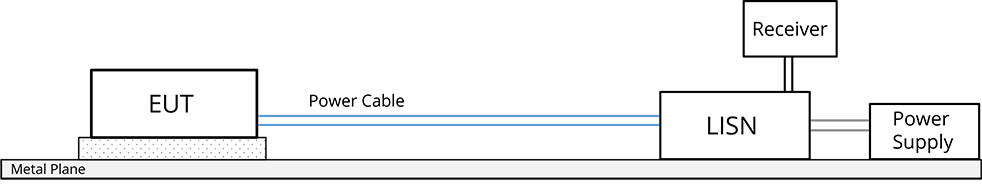
Conducted emissions tests generally measure the noise voltage a product places on its power inputs. The voltage is measured in the frequency domain using a spectrum analyzer or an EMI test receiver. These tests employ a device called a Line Impedance Stabilization Network (LISN)1 that provides a stable impedance for the measurement while protecting the receiver from noise and potentially high power-supply voltages.
For power line measurements, the LISN is placed between the power source and the equipment under test (EUT),2 as illustrated in Figure 1. The voltage is measured from each power phase to system ground. The LISN impedance is 50 Ω for power line measurements. Standards that require conducted emissions testing of communication lines typically call for a 150-Ω LISN.

Figure 2 shows a 50-Ω LISN schematic. The 50-µH inductor and 1-µF capacitor attenuate any high-frequency noise coming from the power source. The 0.1-µF capacitor protects the receiver from the low-frequency power voltage. Limits are typically specified in µV or dB(µV) and are rms values. There may be different limits for peak, quasi-peak and average power measurements. Peak, quasi-peak, and average detectors are described in a Level 4 article on this website.
Radiated Emissions
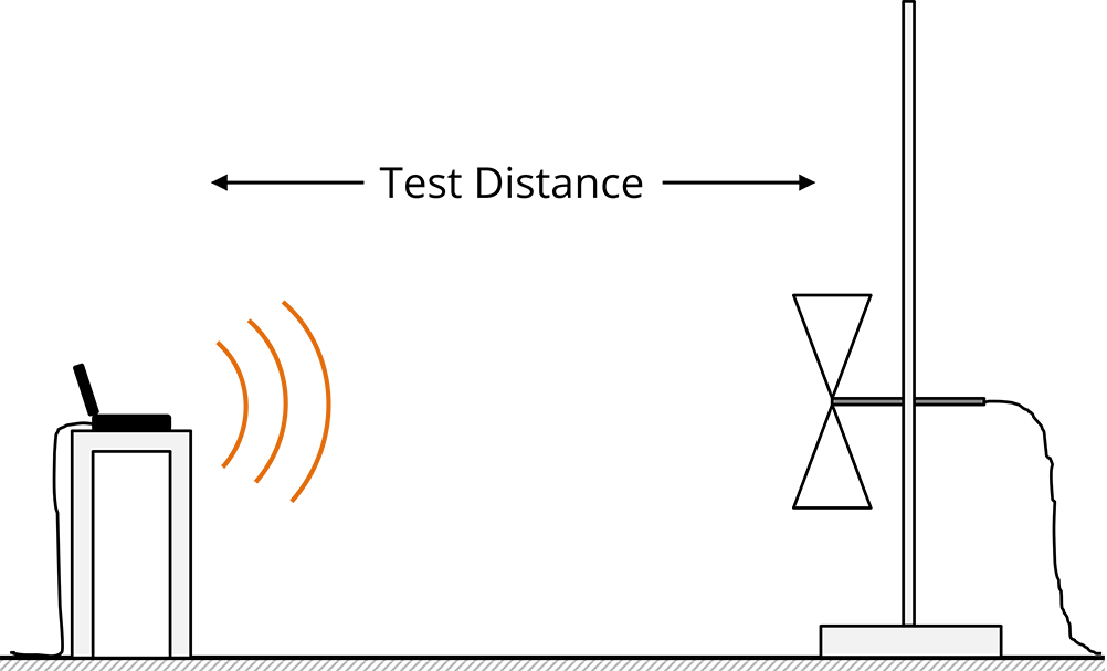
Radiated emissions testing is typically performed by placing an antenna at a given test distance from the EUT, as illustrated in Figure 3. This is usually done in an open field or in a shielded semi-anechoic room. Electromagnetic emissions picked up by the antenna are measured using a spectrum analyzer or an EMI test receiver. The product is non-compliant if the measured field strength at any test frequency is above the specified limit. Limits are typically specified in µV/m or dB(µV/m) and are rms values. As with conducted emissions measurements, there may be different limits for peak, quasi-peak and average power measurements.
At frequencies below 30 MHz, the receiving antenna is typically a rod antenna (electrically short monopole). Biconical antennas are generally used between 30 MHz and 200 MHz. Log-periodic arrays or large horn antennas may be used from 200 MHz to 1 GHz, and horn antennas are typically used above 1 GHz.
Radiated Immunity
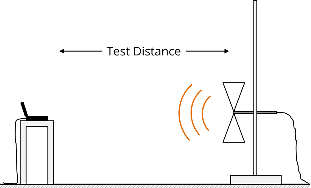
Radiated immunity testing is generally performed using a transmitting antenna located a given test distance from the EUT, as illustrated in Figure 4. This is usually done in a shielded semi-anechoic room. The EUT is subjected to an electric field at various frequencies. Generally, the product must function without error when subjected to a specified minimum field strength.
Dwell time (the time spent testing at each frequency) is an important test parameter. The EUT must be illuminated at a given frequency long enough to run through all of its operating states. Tests may require continuous wave (CW) sources that emit a sine wave and/or modulated sources that simulate interference from certain intentional transmitters.
Due to the difficulty of generating strong radiated electric fields at low frequencies (e.g., below 100 MHz), low-frequency radiated immunity tests are often performed by placing the EUT in some type of waveguiding structure, such as a TEM or GTEM cell.3
For radiated immunity tests, limits are typically specified in V/m and are rms values. Test procedures may specify different field strength levels corresponding to the severity of the failure. For example, at 10 V/m, merely annoying behavior may be ok, while product behavior that affects operator safety may need to meet a much more stringent field-strength requirement. Field strength levels also vary across frequency bands, depending on the EM environment where the product is likely to be used.
While swept-frequency electric-field immunity is the most common type of radiated immunity testing, other radiated immunity tests evaluate magnetic-field and transient-field immunity.
Finally, it is important to note that international immunity standards have not kept up with the rapid introduction of new transmitter technologies and protocols. Many companies have their own internal radiated immunity test procedures designed to ensure that their products won’t be affected by newer phone models, near-field transmitters, and other interference sources not covered by international standards.
Electrical Fast Transients (EFT)
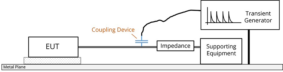
Electrical Fast Transient (EFT) immunity tests are primarily designed to emulate the noise created when the current to an inductive load is switched off. As illustrated in Figure 5, a transient generator produces voltage spikes with a specified amplitude and duration. These voltage transients are coupled to the EUT wiring harness. The EUT must continue to operate normally, or with acceptable errors, in the presence of the coupled transients.
Different standards specify different coupling networks. In addition to the capacitive coupling illustrated in the figure, transients may be coupled through a direct connection or through a transformer. The injected voltage and current waveforms depend on the coupling network and the EUT impedances. The coupled waveforms generally differ significantly from the source waveforms described in the specification.
Lightning
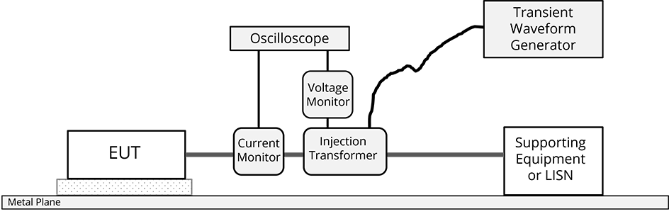
There is no international standard for lightning testing that involves striking the product with a massive air discharge. Lightning immunity testing is performed by injecting high-energy transients into the cables attached to specific component inputs, as illustrated in Figure 1.8. The voltage waveform of the transient source and/or the injected current is specified and monitored. For communication cables, the end of the cable opposite the EUT is connected to transient-protected supporting equipment. For power lines, the end of the cable opposite the EUT is connected to an LISN.
The types of waveforms injected depend on how and where the EUT is installed. Military and aerospace lightning transients are typically applied in multiple strokes spaced tens of milliseconds apart and/or bursts, each containing numerous transients spaced about a millisecond apart.
Most automotive and consumer products are not subjected to lightning immunity testing. Lightning tests are typically limited to products that connect to the telephone network or to devices with communication cables that extend long distances.
Electrostatic Discharge
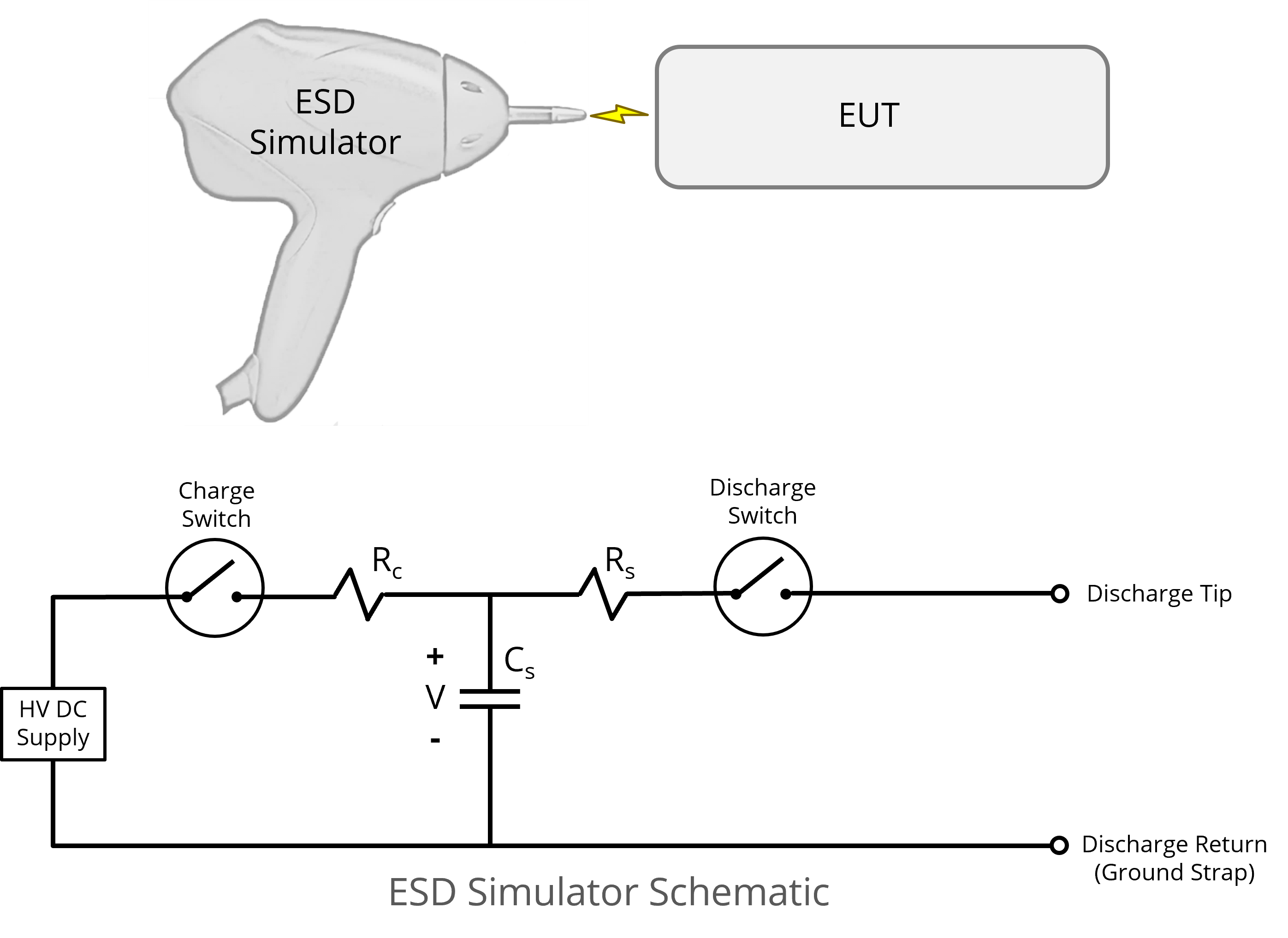
Electrostatic discharge testing simulates the effect of a charged person or device making contact and discharging to the EUT. Electric charge stored in a capacitor is discharged to the EUT through a resistance. A simple ESD simulator schematic is shown in Figure 1.9. Larger capacitances result in higher energy discharges. Lower resistances result in higher peak currents.
Tabletop products are typically tested on a non-conducting table with a metal top. Floor-standing products are tested on a metal floor. Tests can be conducted by bringing the simulator close to various points on the EUT until a discharge occurs (air discharge) or by making metal-to-metal contact between the simulator and the EUT before triggering the simulator (contact discharge).
ESD test limits generally depend on the type of failure observed. The limit may be low for non-critical, self-correcting errors (e.g., ~2,000 V). On the other hand, critical errors, such as damage to the EUT or a shutdown of a vital system, are usually unacceptable, even at the highest simulator voltage.
Bulk Current Injection (BCI)
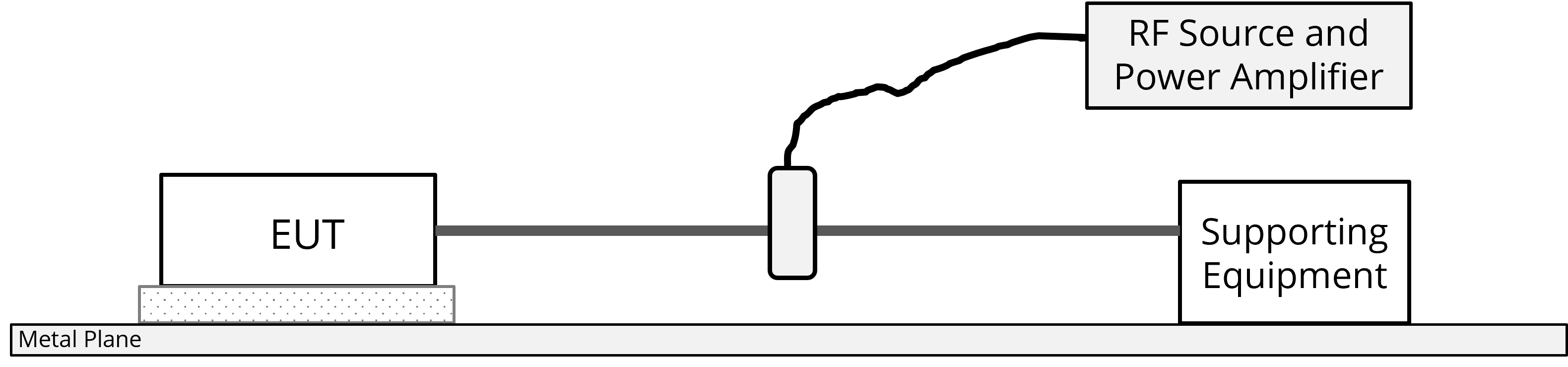
Bulk current injection testing is intended to simulate radiated interference at long wavelengths, where noise will likely couple to the EUT through the wiring harness. The basic test setup is illustrated in Figure 1.10. A current injection probe is used to transformer-couple RF currents onto a wiring harness attached to the EUT. The equipment must perform without error when subjected to a specified injection current.
Most consumer products do not have a bulk current injection test requirement. However, it is commonly required in automotive and aerospace systems, where components are often connected via long wiring harnesses.
Two categories of BCI tests employ different methods to determine when the specified injection current has been achieved. These categories are substitution and closed-loop. The substitution method calls for a preliminary calibration test using a 50‑Ω calibration fixture in place of the EUT, harness and support equipment. The forward power from the transmitter required to produce the specified current at each test frequency is recorded. The test is then repeated with the EUT in place. Instead of monitoring the current, the test is performed with the same forward power that produced that current in the calibration fixture. The closed-loop method directly monitors the current injected into the wiring harness using another current probe. Closed-loop methods may or may not include a forward-power limit determined by a pre-measurement calibration.
When testing components that are not grounded through their chassis, some BCI procedures allow a ground wire to bypass the current-injection probe at low frequencies, giving the current somewhere to go. Others do not allow the ground wire, basically requiring the current to be injected into an open circuit. This generates strong electric fields between the EUT and the metal tabletop.
Power Dips, Drops and Transients
The power distribution system in many environments, such as factories, homes and vehicles, can be very noisy. For example, in a typical home, it would not be uncommon to see occasional voltage spikes as high as several hundred volts or severe drops in the voltage that last several milliseconds. Products must be able to endure these power fluctuations without exhibiting unacceptable behavior.
Specific requirements for immunity to power bus voltage fluctuations depend on the environment where the product will be used. The test procedure typically involves inserting a noise injection device between the EUT and its power source. Power line transients are injected in a manner similar to lightning or EFT transients. Brief power line dips are typically introduced by shorting the power input through a resistance for a few milliseconds. Longer power line drops are performed by removing the power or reducing the power line voltage for a specified period.
- Some standards refer to the LISN as an Artificial Mains Network (AMN). ↩
- Some standards refer to the test object as the DUT (Device Under Test) or UUT (Unit Under Test) instead of EUT. ↩
- The TEM (Transverse ElectroMagnetic) cell and GTEM (Gigahertz Transverse ElectroMagnetic) cell are transmission line structures with expanded dimensions to allow the placement of test devices inside. ↩