
EMC Question of the Week: July 27, 2026
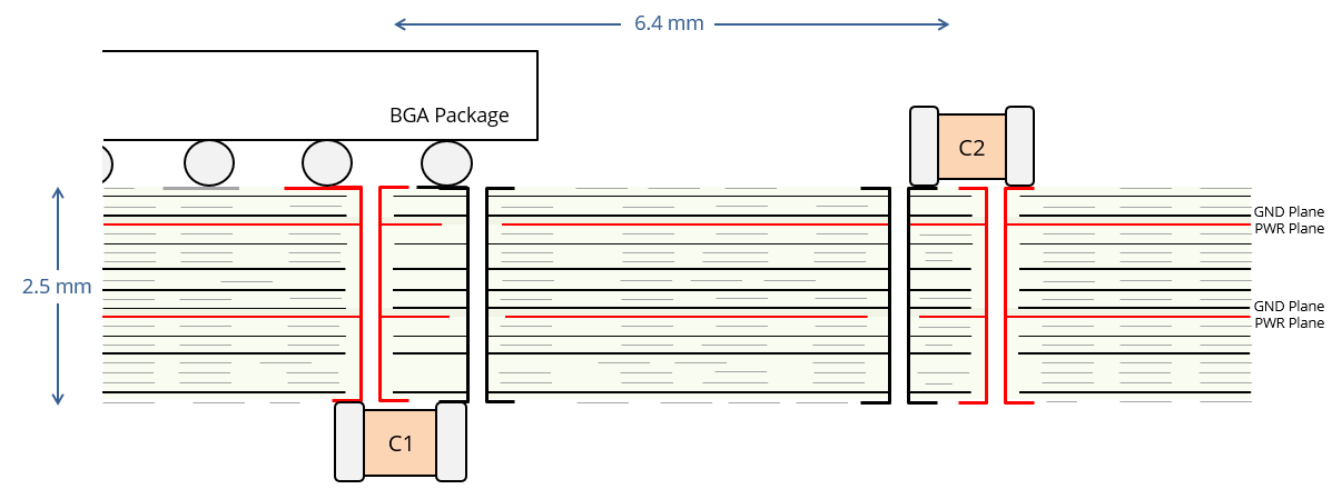
The figure shows a cross-section of a 24-layer circuit board with GND planes on layers 2, 4, 7, 10, 12, 14, 17, 19, and 23. There are PWR planes on layers 5 and 15. Two decoupling capacitors are shown. C1 is on the backside of the board and shares via connections with a BGA. C2 is on the topside of the board and is 6.4 mm away from the BGA. Within the first 200 ps of a sudden demand for current to the BGA, where is most of the current coming from?
- C1
- C2
- C1 and C2 equally
- the plane capacitance
Answer
The best answer is “d.” The closely spaced power planes behave like a radial transmission line with a very low characteristic impedance. The current drawn from the planes ramps up as the wavefront moves outward. After 200 ps, the current is being drawn from a radius of about 28 mm. For a 0.25 mm plane spacing in an FR-4 dielectric, that represents a current of about 1 ampere per volt.
Neither of the decoupling capacitors in this example can respond that fast. C1 is 2.5 mm away and connected through two parallel vias. The vias form a transmission line with a characteristic impedance of about 100 ohms. A sudden 1-volt drop in the voltage at the BGA launches a depletion wave on the vias with a current equal to 1 volt divided by 100 ohms (10 mA). This travels to C1 in about 18 ps. However, even if C1 has infinite capacitance and zero inductance, it cannot immediately supply large amounts of current to the BGA. When the 10-mA current wave hits the ideal capacitor, the impedance mismatch sets up a reflected current wave that is also 10 mA. After one round trip, the current at the BGA is 20 mA. Every successive round trip adds another 20 mA. After 200 ps, 5 round trips to C1 have been completed and the current is about 90 mA. This is far less than the 1000 mA being supplied by the planes.
In the short term, C1 can't compete with the plane pair. Eventually, however, the depletion wave hits the plane boundary. Boards rely on the decoupling capacitors to replenish the charge stored in the planes. In this example, C2 and other capacitors similarly connected on the topside of the board are a little better at replenishing the charge in the upper plane pair due to their shorter via connections. At no time does C1 provide "most of the current."
Of course, two capacitors connected to different BGA pins through different vias could supply twice as much current as C1 alone. Roughly 10 capacitors connected in this manner could supply a current equal to that supplied by one pair of 0.25-mm-spaced planes. On the other hand, reducing the plane spacing from 0.25 mm (10 mils) to 0.125 mm (5 mils) would double the amount of current supplied by the planes.
Getting charge (or energy) from point A to point B quickly is not simply a matter of distance. The impedance of the connection is also important.
Note: For conducted and radiated emissions, the frequency-domain behavior of the decoupling is generally more relevant than the time-domain behavior. In this example, C2 makes a better connection to the planes than C1 at the highest frequencies where the decoupling capacitors are effective. Nevertheless, the high density of vias on the backside of a board under a BGA makes this area unusable for most purposes. It is generally a good idea to utilize this space for small decoupling capacitors (like C1 in this example) rather than leaving it empty.
Have a comment or question regarding this solution? We'd like to hear from you. Email us at