EMC Question of the Week: February 9, 2026
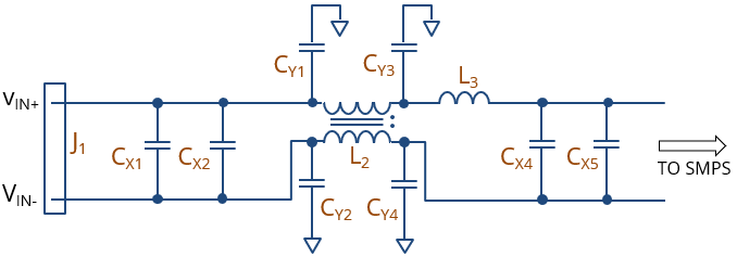
A schematic for an AC power line filter is shown in the figure. The device is located in a metal enclosure. In order to filter the common-mode power bus noise effectively, which of the components shown in the schematic need to be eliminated?
- L2
- L3
- CY1 and CY2
- CY3 and CY4
Answer
The best answer is “b.” Common-mode chokes should only be used to filter balanced conductor pairs. The presence of L3 means one side of the choke sees a different impedance to ground than the other side. In a balanced system, common-mode sources that drive both lines relative to the board ground are effectively filtered by the common-mode choke and the Y-capacitors. Differential-mode sources are effectively filtered by the X-capacitors with help from the leakage inductance of the choke.
L3 attenuates the voltage on one line relative to ground without attenuating the voltage on the other line relative to ground. It creates an unbalanced LC filter next to the balanced CM choke. The change in electrical balance causes mode conversion and parasitic coupling challenges that generally degrade the performance of the entire filter. No filter should ever be designed this way. If needed, L3 could be replaced with two identical inductors located on each line. Alternatively, L3 could be moved to the right of CX4 and CX5, and we could rely on CX4, CX5, CY3, and CY4 to establish electrical balance (at high frequencies) to the right of the choke.
BTW: If you chose (c.) or (d.), it may be that you've heard that Y-capacitors should never be located on both sides of a common-mode choke. That is simply not true. Yes, there are some applications where the common-mode source drives the entire circuit board relative to infinity (or a remote system ground). And, in those cases, Y-capacitors on both sides of the choke allow common-mode currents to bypass the choke. In those cases, Y-capacitors (and the ground plane itself) should be eliminated on one side of the choke. A good example of this is filtering high-frequency differential signals on unshielded twisted wire pairs.
Nevertheless, in applications like the one described here, circuits on the board do not drive the board relative to system ground (the board is in a metal enclosure). Any common-mode sources are driving the power lines relative to the board/enclosure ground. In this case, we need to filter these lines to the board/enclosure ground. This is usually best accomplished using Y-capacitors on both sides of the choke to form a pi-filter.
Have a comment or question regarding this solution? We'd like to hear from you. Email us at