
Chapter 8 Exercise: Ground vs. Current Return
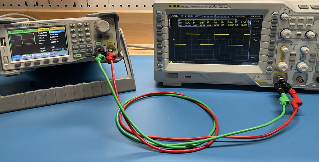
This exercise demonstrates that the intended current path is not always the path that most of the current takes.
Preparation: It is helpful if students have done some of the previous laboratory exercises in this course where the measured results closely agreed with the expected results.
Equipment Required:
- oscilloscope (at least 100-MHz bandwidth)
- waveform generator
- 2 coaxial-to-wire-pair adapters
- 2 wires (preferably similar, but different colors)
Procedure:
Step 1: Connect the waveform generator to the oscilloscope (both powered from wall outlets) through a wire pair and measure a 1-kHz square wave.
Step 2: Reverse the wires on one side and repeat the measurement. In one position, the measurement should look good, but when the signal side of the source is connected to the ground side of the oscilloscope, the waveform will be drastically different (perhaps not even measurable)
Step 3: Ensure that one of the wires connects to the ground on both sides (good measurement) and then disconnect the other wire (no signal)
Step 4: Reconnect the signal wire and disconnect the ground wire. Depending on the inductance of the ground connection, the 1-kHz signal should still be observable.
Step 5: Repeat the same measurements with a 10-MHz square wave.
Step 6: Explain the difference and create a first-order RL model that fits all of the measurement results reasonably well.
Notes:
The measurements could also be repeated with a battery-powered waveform generator or scope to eliminate the hidden return path.