
Chapter 7 Lab Exercise: Measuring Common-Mode and Differential-Mode Signals
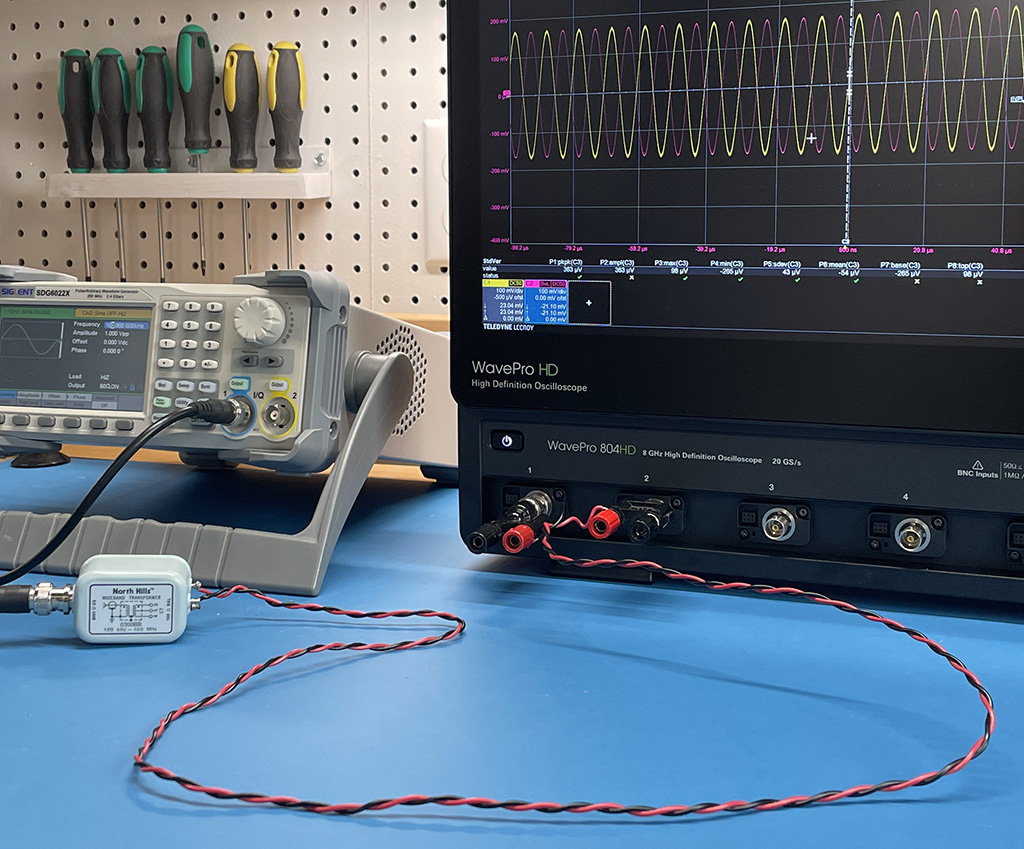
Most power and signal distribution is differential-mode (relative to a zero-volt reference at infinity). Noise coupled to or from power and signals tends to be common-mode. Understanding how these modes are defined is a critical first step to understanding how noise couples to and from circuits.
Preparation: Students should have completed Chapter 7 and worked the problems at the end of the chapter.
Equipment Required:
- waveform generator
- 3-channel digital oscilloscope with basic math capabilities
- 3-wire power cord or similar cable
- balun or isolation transformer
Procedure:
Step 1: Set the waveform generator to produce a 100 Hz sine wave with an amplitude of 1 volt. Connect the output to the unbalanced side of the balun (or primary of an isolation transformer).
Step 2: Connect the balanced side of the balun to the two power wires in the power cord. Connect the ground wire in the power cord to the ground on the unbalanced side of the balun (which is also the generator ground).
Step 3: At the other side of the power cord, use adapters to connect the center conductors of the scope Channels 1 and 2 to the power wires. Connect the grounded side of Channels 1 and 2 to the ground wire of the power cord.
Step 4: In this configuration, the scope behaves like a pair of LISNs. Each channel is 50 Ω to ground. The generator and isolation transformer generate a differential-mode signal.
Step 5: Compare the signal on Channel 1 to the signal on Channel 2. They should look identical, but 180° out of phase. Use the math function to subtract the Channel 2 signal from the Channel 1 signal. This displays a voltage that is twice the differential-mode component of the signals on the power cord. Record the differential-mode voltage.
Step 6: Use the math function to add the Channel 2 signal to the Channel 1 signal. This displays a voltage that is twice the voltage of the common-mode component of the signal. Record the common-mode voltage.
Step 7: Remove the balun and drive both power wires with the same signal relative to the generator ground. Use the math function to subtract the Channel 2 signal from the Channel 1 signal. This displays a voltage that is twice the differential-mode component of the signals on the power cord. Record the differential-mode voltage.
Step 8: Use the math function to add the Channel 2 signal to the Channel 1 signal. This displays a voltage that is twice the voltage of the common-mode component of the signal. Record the common-mode voltage.
Step 9: Use a common-mode current probe to measure the common-mode current on the power conductor pair. This should be equal to the common-mode voltage divided by the 25-Ω common-mode impedance.
Step 10: Remove or disconnect the ground wire in the power cord. What effect does this have on the measured common-mode voltage and current? Why?
Step 11: Increase the frequency of the signal source from 100 Hz to 10 MHz while observing the common-mode current. Where is the current going?
Notes:
This exercise can be done with a battery-powered generator and/or oscilloscope to eliminate the current return path through the safety ground. This causes the common-mode current to drop to near zero when the ground wire is disconnected at 100 Hz. However, significant common-mode current will still be observed at MHz frequencies. The common-mode voltage on the oscilloscope channels can be compared to conducted emissions limits.