
Chapter 6 Lab Exercise: Measuring Crosstalk in a Cable Harness
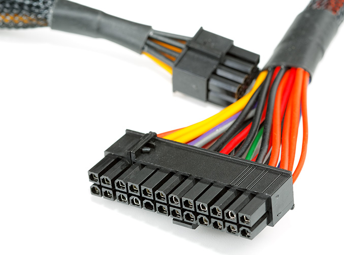
Unlike the previous exercises that have the students measuring crosstalk and coupling, this exercise is performed with cables that don't have a well-defined geometry. Many wiring harnesses have a cross-sectional geometry that changes as signals propagate from one end to the other. Estimating the crosstalk in these cables is generally important, even if it can't be determined precisely.
Preparation: Students should have completed Chapter 6.
Equipment Required:
- a 10-meter cable harness with at least 5-10 wires
- waveform generator
- 2-channel oscilloscope (input impedance = 50 Ω)
Procedure:
Step 1: Number the wires from 0 to N-1, where N is the number of wires in the cable harness. Wire 0 will be the designated 0-volt reference for our single-ended signals. Bring the ends of the harness near each other and measure the resistance of Wire 0.
Step 2: If one of the other wires in the harness carried 1 A of current that returned on Wire 0, what would the worst-case voltage coupled to other circuits utilizing Wire 0 be? Validate this by driving Wire 1 with a 10-volt, 60-Hz sinusoidal signal. At the opposite end of the cable, connect Wire 1 to Wire 0 through a 10-Ω resistor. Short Wire 2 at one end and measure the voltage coupled to Wire 2 at the other end. How does this voltage compare to your calculation?
Step 3: Short Wire 4 to Wire 0 at both ends of the harness. What effect does this have on the coupled voltage? Why? Once this question has been answered, remove the connections to Wire 4.
Step 4: Without changing the wire terminations, reduce the source voltage to 1 volt and increase the frequency to 100 kHz. Measure the voltage coupled to Wire 2. Is this still common-impedance coupling? One way to know for sure is to reduce the measurement frequency to 10 kHz and see how much the coupled voltage changes. Try this and explain the results you get. Use this result to calculate L12.
Step 5: Short Wire 4 to Wire 0 at both ends of the harness. What effect does this have on the coupled voltage? Why? Once this question has been answered, remove the connections to Wire 4.
Step 6: Remove the 10-Ω resistor from Wire 1 and open the shorted end of Wire 2. Measure the voltage coupled to Wire 2 at 100 kHz and use this result to calculate C12.
Step 7: Short Wire 4 to Wire 0 at both ends of the harness. What effect does this have on the coupled voltage? Why? Once this question has been answered, remove the connections to Wire 4.
Step 8: Estimate the time it takes for a signal to propagate the length of the cable. Suppose the waveform generator produced a 10-ns pulse with a repetition rate of 1000 ns. What would you expect the coupled waveform to look like?
Step 9: After you've answered the question in Step 5, set the waveform generator to produce a 10-ns pulse with a repetition rate of 1000 ns. How does the measured waveform compare to your expectation?
Step 10: How do you expect the coupled waveform to change if you short Wire 4 at both ends? Try this and see if you were right.
Notes:
In Step 2, an AC power supply can be substituted for the waveform generator if necessary to get 1 A of current. Alternatively, the waveform generator can be scaled down to provide 10 mA of current, and the measured coupled voltage can be multiplied by a factor of 100.
A key point of this exercise is that at low frequencies (i.e., when the cable is less than a quarter wavelength long), the crosstalk is highly dependent on the cable terminations. The termination impedances determine which coupling mechanisms will dominate. On the other hand, at frequencies where the cable is electrically long, the coupling is relatively independent of the terminations, but unmatched terminations will create reflections. In the time domain, these reflections can cause coupled pulses to bounce around. In the frequency domain, these reflections create standing waves.