
Chapter 6 Lab Exercise: Measuring Time-Domain Crosstalk Between Microstrip Traces
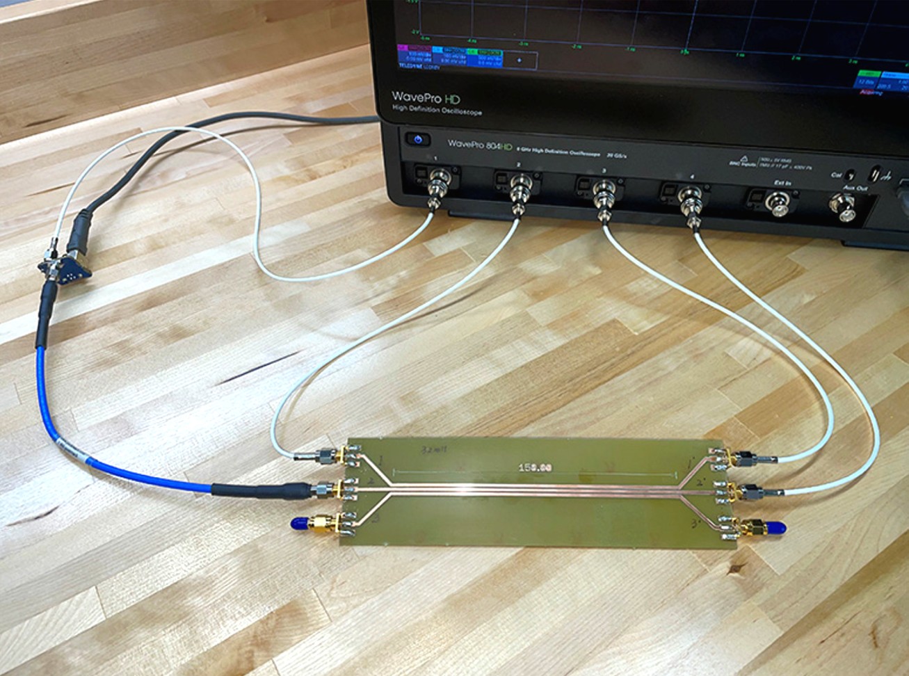
Crosstalk (or coupling) in circuit boards can also be measured in the time domain. Time-domain crosstalk is directly applicable to the impact that unwanted coupling has on signal integrity.
Preparation: This exercise requires a special test board with SMA connectors and parallel traces. These boards are relatively easy to design. PCB fabricators can build them in small quantities at a cost of a few hundred dollars per board. They can also be purchased from various companies that specialize in EMC or SI education.
Equipment Required:
- a test board with parallel microstrip traces and low-inductance connectors
- fast step-waveform generator
- 4-channel oscilloscope (≥1 GHz)
Procedure:
Step 1: Connect the pulse generator to one of the traces. Connect the other end to Channel 4 of the oscilloscope.
Step 2: Connect the near and far ends of the other trace to Channels 2 and 3, respectively. All of the cables connected to Channels 2-4 should have the same length.
Step 3: Observe (and trigger on) the step function in Channel 4. Adjust the amplitude of Channels 2 and 3 to show the coupled waveforms.
Step 4: Compare the observed waveforms with the waveforms plotted in Figure 6.15 of the text. From the measured results, determine the end-to-end time delay of the traces and the amplitude of the near- and far-end crosstalk. Be sure to account for the time-delay in the connecting cables.
Step 5: Place a sheet of FR-4 circuit board stock over the top of the test board to simulate a microstrip geometry. What happens to the far-end crosstalk? Why?
Notes:
If this is the same test board used to measure the crosstalk in the frequency domain, students can be asked to calculate the time-domain response prior to completing this lab.