
Chapter 6 Lab Exercise: Measuring Frequency-Domain Crosstalk Between Microstrip Traces
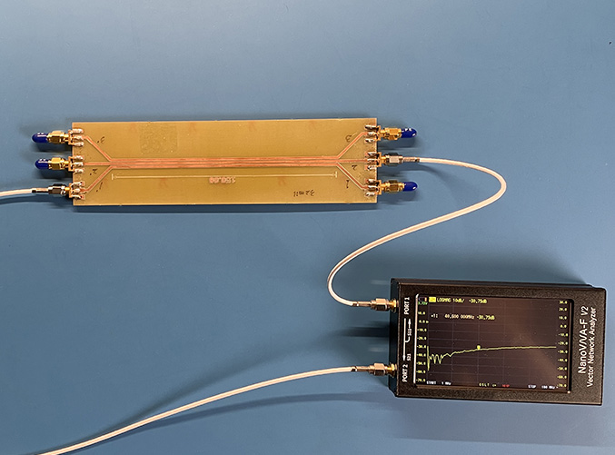
Crosstalk between printed circuit board traces is a matter of great importance to both EMC and signal integrity engineers. Many circuit board layouts require high-speed traces to be routed parallel to each other. If the traces are too close, the crosstalk might be unacceptable. But how close is too close?
Preparation: This exercise requires a special test board with SMA connectors and parallel traces. These boards are relatively easy to design. PCB fabricators can build them in small quantities at a cost of a few hundred dollars per board. These boards can also be purchased from various companies that specialize in EMC or SI education.
Equipment Required:
- a test board with parallel microstrip traces and low-inductance connectors
- vector network analyzer
- 2 50-Ω terminators
Procedure:
Step 1: Students should measure the board and trace geometry, including the length and width of the traces, distance between traces, and trace height.
Step 2: Students should calculate the expected crosstalk due to common-impedance coupling at DC and 100 MHz. This should be extremely small at both frequencies and won't affect the measurements in this exercise.
Step 3: Using the VNA, students can drive one trace through Port 1 and measure the voltage coupled to the second trace through Port 2.
Step 4: With an open termination on the far end of the source trace and a matched termination on the near end of the victim trace, plot S21. Choose any frequency where S21 increases linearly with frequency to determine the amount of capacitive crosstalk. Calculate the value of C12.
Step 5: The crosstalk should level off at a value equal to C12/C22. Use this to estimate the value of C22.
Step 6: Short the far end of the source trace and the near end of the victim trace. Use the measured plot of S21 to calculate L12 and L22.
Step 7: Note that the traces have the same geometry, so L11=L22 and C11=C22. Using the measured values of L22, L12, C22, and C12, calculate the expected near-end and far-end crosstalk when both traces have matched 50-Ω terminations.
Step 8: Terminate the unconnected ends of the traces with 50-Ω terminators and measure the near-end and far-end crosstalk. Compare your results to the expected values. Why isn't the far-end crosstalk zero?
Notes:
Once the L and C parameters are known, the time-domain coupling can be determined. A pulse generator and a 2-channel oscilloscope can be used to measure the near-end and far-end coupling in the time domain.