
Chapter 5 Lab Exercise: Measuring Characteristic Impedance and Propagation Velocity (Method 2)
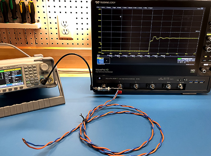
The characteristic impedance and propagation velocity of a cable can also be measured in the time domain. This can be done directly with a TDR or using a fast oscilloscope, a short pulse generator, and a long cable.
Preparation: Students should read Chapter 5.
Equipment Required:
- fast pulse or step function generator (e.g., transition times ≤100 ps)
- fast oscilloscope (≥1 GHz)
- about 2 meters of cable
Procedure:
Step 1: Connect the middle of the T-connector to Channel 1 of the oscilloscope. Connect the pulse generator to one side of the T-connector through any length of 50-Ω coaxial cable.
Step 2: Set the Channel 1 input impedance to 50 Ω and the time base to 10 ns/div. Turn on the pulse generator and adjust the setting of the oscilloscope so that the voltage step is clearly visible. Note the amplitude of the step and the transition time.
Step 3: Connect a 50-Ω terminator (or Channel 2) to the other side of the T-connector and note the change in the amplitude of the measured pulse. If both the generator and Channel 1 are 50 Ω, then another 50 Ω in parallel would reduce the measured voltage by a factor of 33%. If this is close to the reduction observed, then the pulse generator has an output impedance of 50 Ω, and the combination of the pulse generator and Channel 1 input behaves like a 25-Ω source. If you measured a reduction less than 33%, the pulse generator has a lower output impedance. Use the measured value of the reduction to calculate the effective impedance of the generator in parallel with Channel 1.
Step 4: Remove the 50-Ω terminator and connect that side of the T-connector to the 2-meter cable to be measured. Leave the far end of the cable open-circuited. The amplitude of the waveform prior to seeing the reflected step can be used to estimate the characteristic impedance of the cable using a calculation similar to the one described in the previous step.
Step 5: With the time base set to 10 ns/div, you should now observe the initial step in voltage plus the reflection from the far side of the cable in Channel 1. Twice the length of the cable divided by the time delay is the velocity of propagation.
Step 6: Connect the far side of the cable to a known resistance with a value that is close to the expected characteristic impedance of the cable. The amplitude of the reflected signal will be relatively small. If it is zero, the characteristic impedance of the cable is equal to the known resistance at the termination. If it is not zero, the amplitude of the reflected pulse can be used to determine the reflection coefficient. The reflection coefficient and the known termination resistance can be used to accurately determine the characteristic impedance of the cable.
Notes:
Longer cable lengths allow this exercise to be completed with slower equipment.
Students can be asked to measure several cables with different characteristic impedances. Two of these cables could be the same cables evaluated using the frequency domain measurements in the previous exercise.