
Chapter 3 Lab Exercise: Magnetic-Field Coupling in a Ribbon Cable
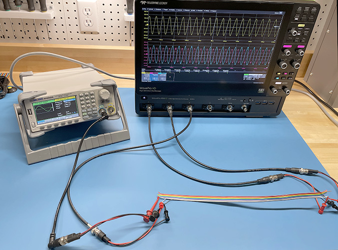
Two circuits sharing a 50-cm length of ribbon cable exhibit measurable levels of all three types of EM coupling. This lab exercise emphasizes the magnetic-field coupling. It can be combined with the common-impedance and electric-field coupling exercises that use almost the same test set-up.
Preparation: Students should be provided with the dimensions of the ribbon cable and parameters of the test set-up before coming to the lab. They should calculate the expected value of the magnetic-field coupling before making any measurements. (This could be done as part of an earlier homework assignment.)
Equipment Required:
- RF signal source (100 Hz to 10 MHz)
- 2-channel oscilloscope
- 50-cm length of ribbon cable with at least 3 wires
Procedure:
Step 1: Connect the RF source to Channel 1 of the oscilloscope through wires 1 and 2 of the ribbon cable. Wire 1 should be connected to the grounded side of both instruments. Set the input impedance of Channel 1 to 50 Ω.
Step 2: Channel 2 of the oscilloscope should be connected to measure the voltage induced on wire 3. The ground side of Channel 2 should be connected to wire 1 and the signal side to wire 3. Set the input impedance of Channel 2 to 50 Ω.
Step 3: Short the opposite side of wire 3 to wire 1. Explain why doing this prevents Channel 2 from picking up any significant electric-field coupling.
Step 4: Starting at 100 Hz, increase the amplitude of the source until there are measurable sinusoidal waveforms on both oscilloscope channels. Channel 1 will have a much higher amplitude than Channel 2.
Step 5: Determine the ratio of the Channel 2 voltage to the Channel 1 voltage. How does this compare to the calculated value of the magnetic-field coupling? Note that (by symmetry) the mutual inductance is equal to half the self-inductance of the Wire 3-1 circuit.
Step 6: Repeat the measurement above at 1 kHz, 10 kHz, 100 kHz, 1 MHz, and 10 MHz. Compare to the calculated values of magnetic-field coupling at those frequencies. Is the agreement good? Is the coupling proportional to frequency? If not, why not?
Step 7: Change the shape of the signal from a sine wave to a square wave. Describe the signal observed in Channel 2. Is this consistent with the expectation for magnetic-field coupling?
Notes:
If the ribbon cable has more than 3 wires, these measurements can be repeated with wires that increase the shared loop area. For example, instead of using wires 1,2 and 3, the measurements can be made using wires 1, 8 and 9. Since magnetic-field coupling depends on the mutual inductance (percentage of shared loop area), the coupling will be stronger (by nearly 6 dB).