What People (and AI Agents) Get Wrong About Common-Mode Filtering
 If you ask ChatGPT how to design a filter to reduce common-mode emissions from your product, you are likely to get some bad advice. This is equally true if you seek guidance from a filter component manufacturer's website or application notes.
There’s no shortage of advice on common-mode filter design, but much of it leaves out the context that determines whether a given approach will actually work. Common-mode filters, for instance, are often characterized by insertion-loss measurements in balanced 50-Ω systems. Those measurements are easy to make and to reproduce, but a balanced 50-Ω system looks nothing like most real-world applications. Another deceptive validation approach is starting with a bad circuit board design and showing that a new layout and several dollars' worth of filter components make it better.
Most of the documents that purport to tell you how to design common-mode filters are sales pitches. Product designers and AI agents read this content believing it is instructional. The advice in these documents gets repeated on social media sites (e.g., LinkedIn) until, ultimately, the issue is so confused that nobody is sure what to believe. Four key points of confusion are:
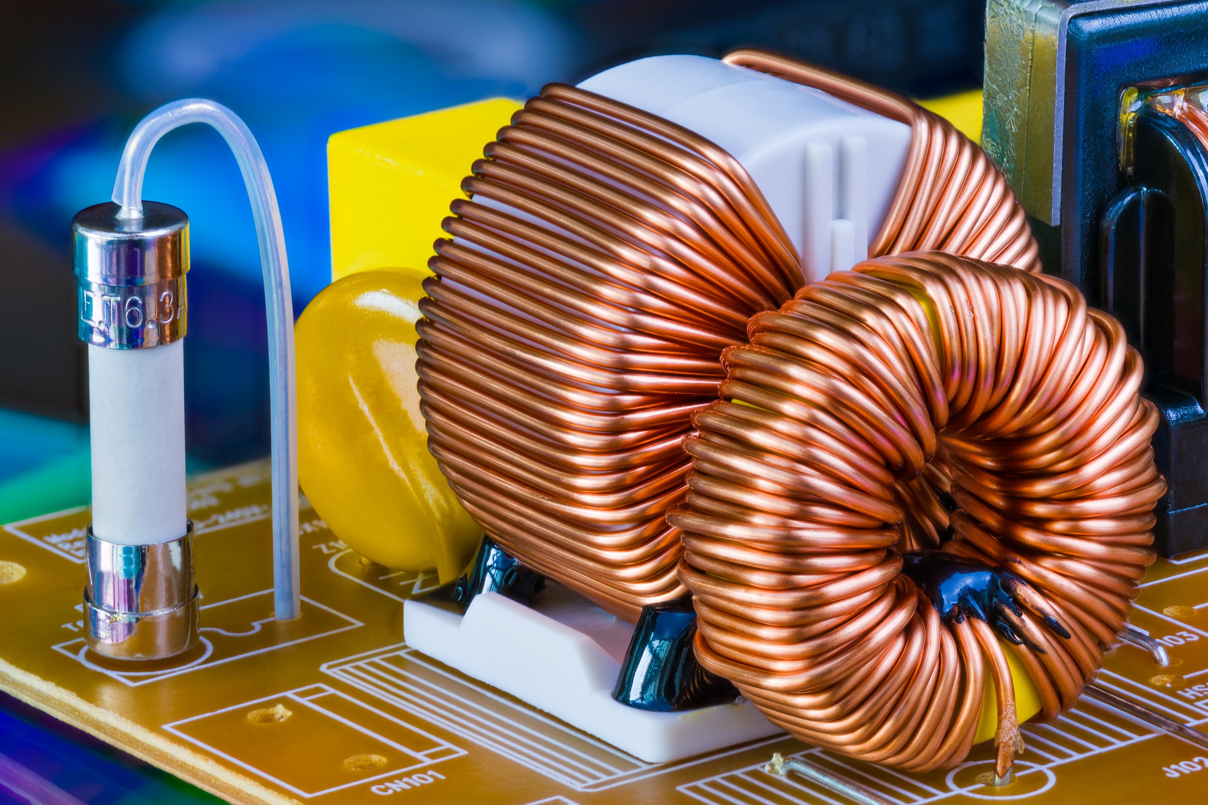
- When is a common-mode choke appropriate? It’s easy to come away with the impression that a choke is almost always called for. In practice, chokes do play an important role in many balanced, unshielded power and signal interfaces, but they’re a poor fit for a lot of the applications where you’ll see them recommended.
- Should Y-capacitors go on both sides of the choke, or on one side only? You’ll find both configurations recommended, sometimes within the same source, usually without a clear explanation of which one is right in a given situation.
- Should the ground plane extend underneath the choke? Should it extend everywhere? Should a hole be cut in the plane beneath the choke? Or should the plane stop where the choke begins? You’ll find each of these conflicting recommendations strongly advocated by various internet sources.
- Should the choke use a low-loss or high-loss ferrite? Is loss in the ferrite material desirable or not? And if it is, why don’t data sheets tell you how much loss a given choke provides?
Despite the wealth of misinformation, common-mode filtering is actually fairly straightforward once a few ideas are in place. Most of the confusion is due to a failure to recognize and understand three important concepts.
- There are two different definitions of common-mode current. In one, the current flows out on the signal or power conductors and returns on a separate ground or return conductor. In the other, it flows out on all of the conductors together and returns as displacement current through the surrounding environment. Both can be reduced by common-mode filtering, but the type of filter required is very different in each case.
- It’s commonly assumed that a common-mode choke impedes common-mode current and passes differential-mode current. That’s true in a balanced system, but not in general. Common-mode chokes are balanced components that are usually inappropriate in unbalanced circuits. In an unbalanced circuit, a choke promotes mode conversion. It can put common-mode noise into the signal path and turn signal currents into a common-mode voltage that drives conducted and radiated emissions.
- As noted above, common-mode chokes are usually evaluated in 50-Ω systems. Designing a filter that looks good in a 50-Ω system is very different from designing one that will attenuate conducted or radiated emissions in a real product.
If you’d like to see how common-mode filtering should be done, I’d recommend our website tutorial at learnemc.com/cm-filtering. Once you understand the nature of the common-mode source in a particular application, designing an appropriate filter is relatively straightforward.
So how do you decide what sources to trust? A good place to start is to see how those sources address each of the four key points of confusion listed above.
When is a common-mode choke appropriate?
In most cases, a common-mode choke belongs in a system where the source, load, and transmission path are all electrically balanced. Good examples include most AC power inputs and high-speed differential signaling. A choke is generally not the right tool for an inherently unbalanced interface such as unbalanced DC power or a single-ended signal. In an unbalanced system, a choke converts some of the differential signal into common-mode noise and injects common-mode noise back into the signal path.
Should Y-capacitors go on one side of the choke or both?
If you’re filtering common-mode current that returns on a ground plane, the Y-capacitors belong on both sides of the choke. This creates a pi-filter that can be very effective, and it’s a common arrangement on AC (or isolated DC) power inputs. If instead you’re filtering common-mode current that returns as displacement current, the Y-capacitors belong on the product side of the filter only. They should not be placed on the cable side.
Should the ground plane extend underneath the choke?
If there are Y-capacitors on both sides, the answer is yes. The ground plane is needed to help the common-mode currents return to their source. If the common-mode current is returning as displacement current, the answer is no. In that case, a continuous ground plane can carry the current around the choke and keep it from doing its job.
Should the ferrite be low-loss or high-loss?
It depends on what the choke is being asked to do. In a power-line filter, where the choke acts as an inductor in a pi-filter, a relatively low-loss ferrite is generally fine, though some loss in the tens-of-megahertz range is welcome because it helps damp resonances. For a filter that has to block common-mode current returning as displacement current, high-frequency loss is essential. The choke’s inductive reactance doesn’t block that current; it only creates or shifts a resonance. A choke works in this situation only when it provides a significant amount of high-frequency resistance, much as a ferrite core or clamp does.
The bottom line
The bottom line is that deciding how and when to use a common-mode choke is highly dependent on the application as well as the source of the common-mode current. Be wary of app notes and internet sources that give general guidance without considering the points discussed above.